
Automatic cleaning device of pump cavity of oil pump

An automatic cleaning, oil pump technology, applied in mechanical equipment, engine components, engine lubrication, etc., can solve problems such as not being able to guarantee 100% cleaning, product quality risks, skin damage, etc., to achieve good market prospects and reduce human body. hazard, low-cost effect

Inactive Publication Date: 2019-02-19
HEFEI KAICHUANG AUTO PARTS
View PDF6 Cites 0 Cited by
  • Summary
  • Abstract
  • Description
  • Claims
  • Application Information

AI Technical Summary

Problems solved by technology

[0003] (1) Manual cleaning varies from person to person and cannot be guaranteed to be 100% clean;
[0004] (2) Employees come into contact with a large amount of kerosene when cleaning, causing damage to human skin;
[0005] (3) If it needs to be cleaned, the pump cover at the pump cavity needs to be disassembled. There is a secondary assembly, which takes man-hours, and the secondary assembly also brings risks to product quality.

Method used


Image

  • Automatic cleaning device of pump cavity of oil pump
  • Automatic cleaning device of pump cavity of oil pump
  • Automatic cleaning device of pump cavity of oil pump

Examples


Embodiment Construction

[0034] In order to make the purpose, technical solutions and advantages of the embodiments of the present invention more clear, the technical solutions in the embodiments of the present invention will be clearly and completely described below in conjunction with the drawings in the embodiments of the present invention.

[0035] In the description of the present invention, it should be noted that unless otherwise specified, the meaning of "plurality" is two or more; the terms "upper", "lower", "left", "right", "inner ", "outside", "front end", "rear end", "top", "bottom" and other indicated orientations or positional relationships are based on the orientations or positional relationships shown in the drawings, and are only for the convenience of describing the present invention and simplifying the Describes, but does not indicate or imply that the device or element referred to must have a specific orientation, be constructed in a specific orientation, and operate in a specific o...


PUM


Abstract

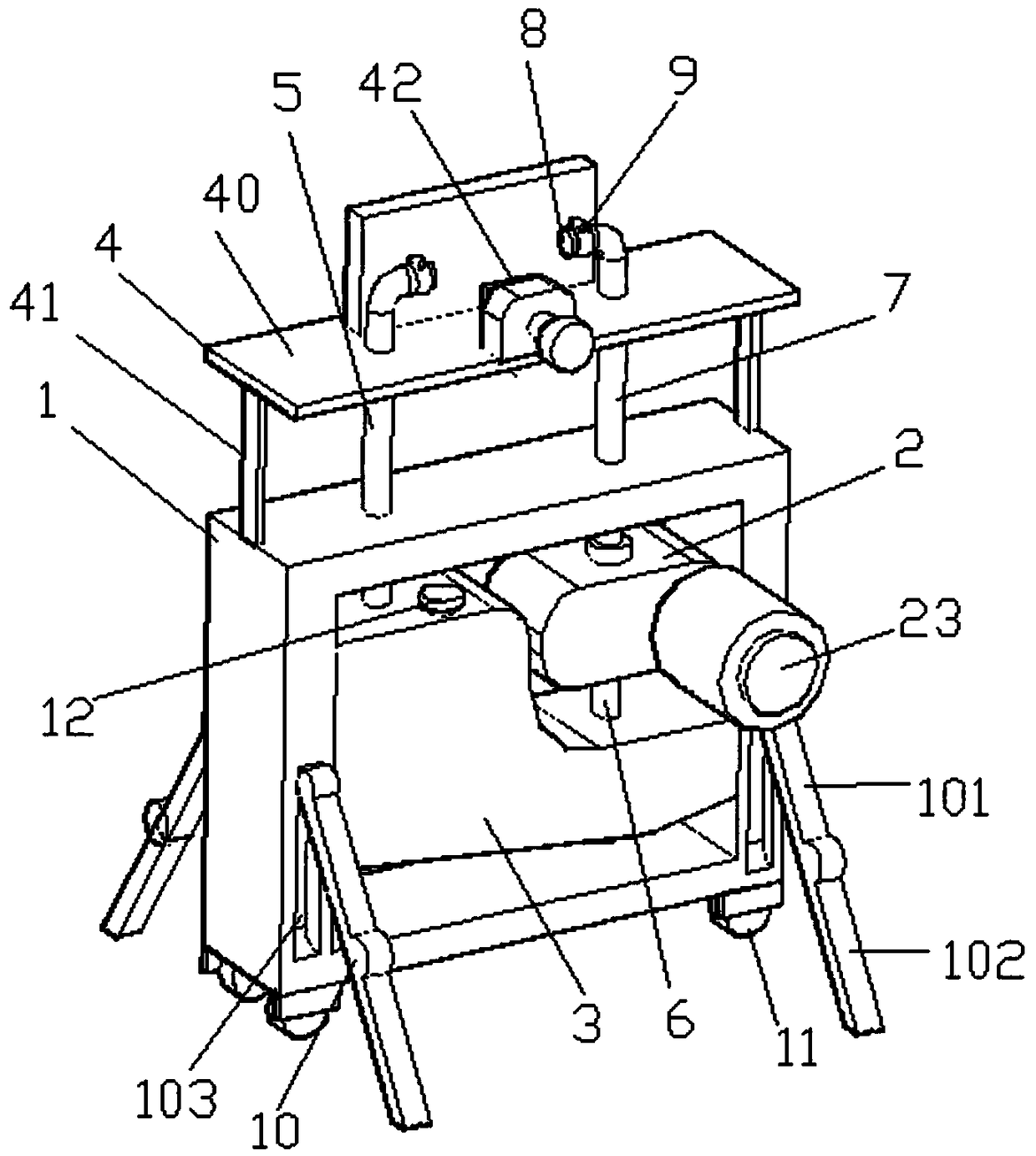
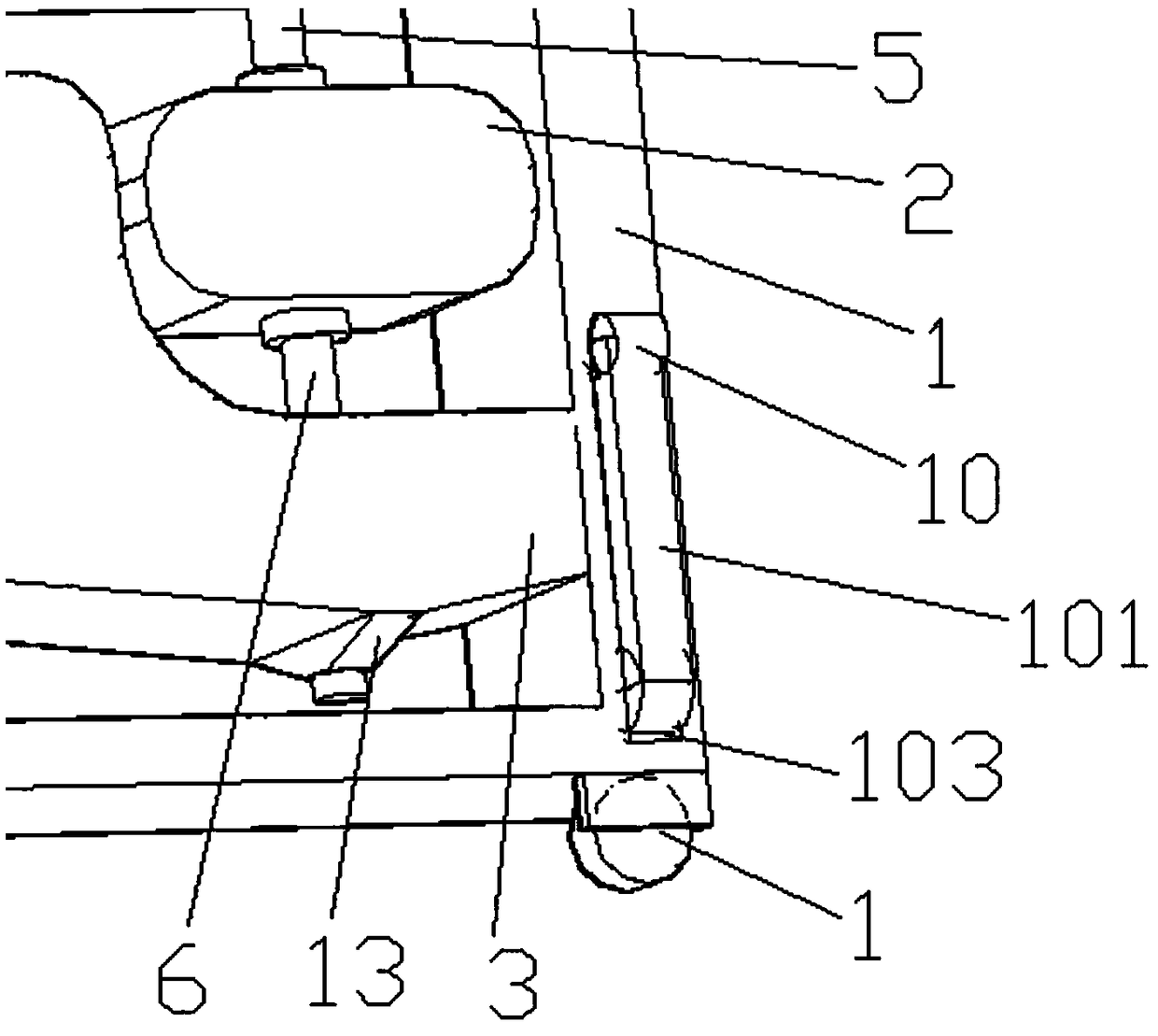
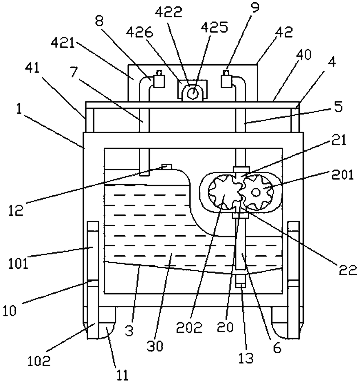
The invention discloses an automatic cleaning device of a pump cavity of an oil pump. The device comprises a machine body, a conveying pump and a liquid storage box are arranged on the machine body, and a cleaning medium is arranged in the liquid storage box; the conveying pump comprises a rotor assembly, a liquid outlet and a liquid inlet, and a power input end of the rotor assembly is connectedwith an electric motor; an oil pump fixing mechanism is arranged above the machine body, a liquid inlet pipe, a conveying pipe and a liquid discharging pipe are further arranged on the machine body, one end of the liquid inlet pipe is connected with the liquid outlet, and the other end of the liquid inlet pipe is arranged on the left side of a fixing platform; one end of the conveying pipe is connected with the liquid inlet, and the other end of the conveying pipe extends to the bottom of the liquid storage box; one end of the liquid discharging pipe is located on the upper part of the liquidstorage box, and the other end of the liquid discharging pipe is arranged on the right side of the fixing platform; rubber hoses are both arranged at the fixing platform end of the liquid inlet pipe and the fixing platform end of the liquid discharging pipe, and hose clamp fastening mechanisms are further arranged on the rubber hoses. According to the device, the structure is simple, operation isconvenient, manual cleaning is not needed, efficiency is extremely high, applicability is good, reliability and safety are achieved, and the device has a good market prospect.

Description

technical field [0001] The invention relates to the technical field of auto parts manufacturing, in particular to an automatic cleaning device for a pump chamber of an oil pump. Background technique [0002] At present, in the field of automotive oil pumps, after the oil pump is assembled, it is necessary to perform a performance test on the oil pump. After the performance test, there is residual oil in the pump cavity, which does not meet the product cleanliness requirements. In the early stage, kerosene cleaning is performed manually. This method has the following three methods: disadvantages: [0003] (1) Manual cleaning varies from person to person and cannot be guaranteed to be 100% clean; [0004] (2) Employees come into contact with a large amount of kerosene when cleaning, causing damage to human skin; [0005] (3) If it needs to be cleaned, the pump cover at the pump cavity needs to be disassembled. There is a secondary assembly, which takes man-hours, and the sec...

Claims


Application Information

Patent Timeline
IPC IPC(8): F16N33/00
CPCF16N33/00
Inventor 曹正荣裴海云贺明学葛田敬
Owner HEFEI KAICHUANG AUTO PARTS
Learn More