Method for quickly placing samples of ground of current collecting line

A collection circuit and basic technology, applied in radio wave measurement systems, satellite radio beacon positioning systems, measurement devices, etc., can solve the problems of difficulty in erecting total stations on steep slopes, high staff requirements, and high possibility of errors. Achieve the effect of realizing precise control of size and position, shortening construction period and reducing error rate

Active Publication Date: 2019-02-19
POWERCHINA SEPCO1 ELECTRIC POWER CONSTR CO LTD
View PDF12 Cites 3 Cited by
  • Summary
  • Abstract
  • Description
  • Claims
  • Application Information

AI Technical Summary

Problems solved by technology

[0009] The objective shortcoming of prior art: the above-mentioned method needs total station or theodolite to measure the angle, requires to be able to see without obstruction, and the collector line is mostly on the mountainous area and steep slope, needs clearing up trees to reach clear view, and steep slope erects total station It is extremely difficult, time-consuming and labor-intensive; before the foundation pit is excavated, the center point and control piles need to be measured outside the excavation range, and after the excavation is completed, the center point and control points must be measured into the foundation pit, which requires multiple times Leading point and turning point, there are many programs and the cumulative error is large; the measurement distance is difficult to meet the site conditions when the pit is divided for the first time, and multiple people are required to cooperate in the measurement. There are many links, the possibility of error is high, and the requirements for staff are high

Method used


Image

  • Method for quickly placing samples of ground of current collecting line
  • Method for quickly placing samples of ground of current collecting line

Examples


Embodiment Construction

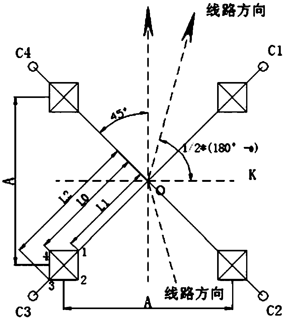
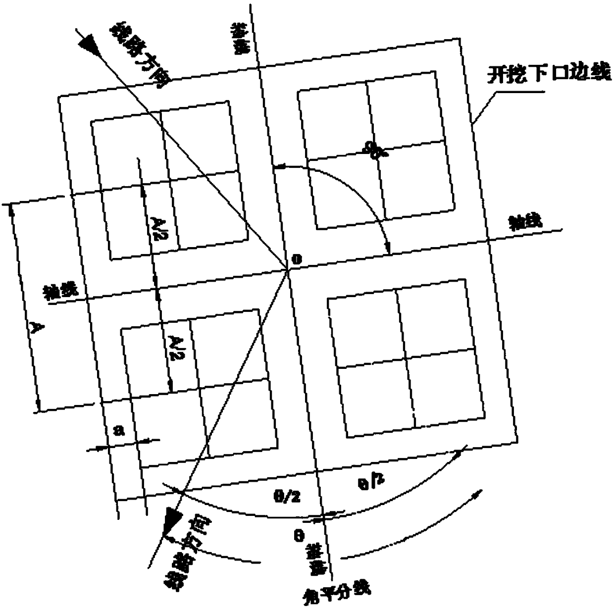
[0022] In order to clearly illustrate the technical features of the present solution, the present invention will be described in detail below through specific implementation methods and in conjunction with the accompanying drawings. The following disclosure provides many different embodiments or examples for implementing different structures of the present invention. To simplify the disclosure of the present invention, components and arrangements of specific examples are described below. Furthermore, the present invention may repeat reference numerals and / or letters in different instances. This repetition is for the purpose of simplicity and clarity and does not in itself indicate a relationship between the various embodiments and / or arrangements discussed. It should be noted that components illustrated in the figures are not necessarily drawn to scale. Descriptions of well-known components and processing techniques and processes are omitted herein to avoid unnecessarily lim...


PUM


Abstract

The invention discloses a method for quickly placing samples of ground of a current collecting line. The method comprises the following steps of: A, inputting coordinates of a center pile of the ground of the collector line into a CAD software, wherein the center point of the ground is O; B, marking a rotation angle theta of the ground; C, making an angle bisector of the rotation angle theta, which is an axis of the ground, and making a vertical line of the axis through the center point O of the ground, wherein the other axis bases on the vertical line, to complete the axes of the ground; D, making two parallel lines of the axes of the ground according to basic dimension given by a draw and a lateral root opening value A, wherein the distance between the parallel lines and the axes is A / 2,and making 4 edges of a pile cap according to the size of the ground; and E, using the CAD software to mark the coordinates of the intersection of the axis and the edges of the excavation bottom, inputting to a GPS measuring instrument, and placing lines according to the coordinates on spot. According to the method for quickly placing samples of the ground of the current collecting line, the needfor multiple measurements and calculations is eliminated, the error rate and work intensity are reduced, and the requirements for operators are reduced.

Description

technical field [0001] The invention relates to the technical field of construction of current collecting lines, in particular to a rapid method for setting out pits for foundations of current collecting lines. Background technique [0002] The stakeout of the foundation of the collector line is based on the center pile and the foundation, and the stakeout is carried out in accordance with the dimensions specified in the design drawings. Collector lines are the key to power transmission. During construction in recent years, there have been many errors in dividing the foundation of the line or the error of dividing the pit is too large, resulting in rework or affecting the safe operation of the line. [0003] At present, the commonly used method of splitting and laying out the current collector line is to use the angle splitting method: [0004] 1) The total station instrument is placed on the center pile O of the tower position. After centering and leveling, the horizontal ...

Claims


Application Information

Patent Timeline
Patent Type & Authority Applications(China)
IPC IPC(8): G01S19/42G01S19/13
CPCG01S19/13G01S19/42
Inventor 林江马海洋郭金伦刘济溶孙超
Owner POWERCHINA SEPCO1 ELECTRIC POWER CONSTR CO LTD
Why Eureka
Try Eureka