Eureka AIR delivers breakthrough ideas for toughest innovation challenges, trusted by R&D personnel around the world.

A tactile touch screen

A touch screen and tactile technology, applied to instruments, electrical digital data processing, input/output process of data processing, etc., can solve the problems of poor restoration of real images, large size, and inability to carry with you, so as to achieve fast information acquisition, Small size and weight, easy to carry effect

Active Publication Date: 2019-02-19
INST OF ELECTRICAL ENG CHINESE ACAD OF SCI
View PDF6 Cites 3 Cited by
  • Summary
  • Abstract
  • Description
  • Claims
  • Application Information

AI Technical Summary

Problems solved by technology

[0010] (1) It is large in size, similar to the size of the current computer monitor screen, and needs to be touched with two hands. The blind person has to touch the entire screen to have a screen of information concept. The speed of obtaining information is relatively slow, and they cannot carry it with them.
[0011] (2) There are generally only two working positions of the touch stick of the existing tactile touch screen, the touch stick or the original position, that is, only images of "black and white" can be displayed, or corresponding to Braille or text characters, while objects in nature The formed images are often in color or grayscale, and the light and shadow changes are continuous. The existing tactile touch screens are extremely poor in restoring real images;
[0012] (3) It can only display pre-stored content, which is generally used as a viewing display, and can only obtain the content input into the display storage unit in advance on fixed occasions. The refresh rate of the display itself is relatively slow, and it takes a few seconds to update a screen of images. Tens of seconds, unable to obtain real-time surrounding information

Method used


Image

  • A tactile touch screen
  • A tactile touch screen
  • A tactile touch screen

Examples


Embodiment 2

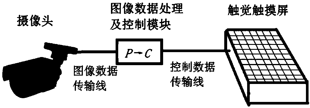
[0067] In embodiment 2 and implementation 3, its control quantity C (ij) is magnetic field strength, light intensity, thermal radiation intensity and voltage respectively, is sent to the signal in each concrete pixel by control data transmission line by image data processing and control module The generator 8, or the voltage lead 10, is used to control the up and down displacement of the contact rod 1.

[0068] Figure 7It is an embodiment of the tactile touch screen of the present invention. It is a matrix composed of single pixels arranged in rows and columns. In the top view, you can see the touch rod 1 of each pixel, and all the touch rods are fixed on the substrate through the telescopic rod 7 (blocked in the figure) 9 or on the fixed plate 6. The 16x12 matrix drawn in the figure can also be a matrix with other numbers of rows and columns. In theory, the smaller the protruding area of ​​the touch rod 1 of a single pixel, the more the number of single pixels that can be a...


PUM


Abstract

A tactile touch screen is disclosed. Real-time scene images are captured by a camera, and are processed into dot matrix gray image in real time, then the gray level signal of each pixel point of the dot matrix gray level image is subjected to matrix transformation to be converted into current and voltage of the controller, infrared, or light intensity signal, which are output to that touch screen,The amount of touch rod displacement at each pixel of the display changes according to the corresponding control signal output amount, and the height of the surface formed by all the dot matrix touchrod combinations on the touch screen is also changed.and the scene image is reproduced in the form of relief. Moreover, with the change of the scene, the corresponding gray touchbar display unit of the display device also changes in real time, so that the blind person can perceive the real-time change of the external scene through the touch screen. The size of the display screen of the inventionis relatively small, similar to the size of a general mahjong, so that a blind person can cover the entire touch screen with the fingertips of the thumb or other fingers.

Description

technical field [0001] The invention relates to a touch screen for visual image display, which belongs to the category of auxiliary identification equipment or auxiliary tools for visually impaired people. Background technique [0002] Blind people can recognize Braille or information on the surface of objects through touch. Traditional Braille is statically "written" on various papers. Later, various electronic dynamic Braille systems were developed. The principle is to simulate the movement of dot matrix touch sticks. Braille, such as figure 1 The electronic Braille system panel developed by the Institute of Electrical Engineering, Chinese Academy of Sciences (IEE CAS) in 2008 is shown. On this basis, a tactile touch screen has been developed. figure 2 It is a large-screen tactile image display developed by researchers in the United States and Japan. [0003] The existing tactile display device uses the executive switch to complete the movement of the touch stick array...

Claims


Application Information

Patent Timeline
IPC IPC(8): G06F3/041
CPCG06F3/0412
Inventor 王厚生
Owner INST OF ELECTRICAL ENG CHINESE ACAD OF SCI
Why Eureka
Eureka Blog
Learn More