AI technical title is built by Patsnap AI team. It summarizes the technical point description of the patent document.
A fuel element and fuel technology, applied in the field of molten salt reactors, can solve problems such as high cost of preparation methods, and achieve the effects of reducing preparation costs, improving utilization ratio, and fast forming speed
Active Publication Date: 2020-05-08
SHANGHAI INST OF APPLIED PHYSICS - CHINESE ACAD OF SCI
View PDF5 Cites 0 Cited by
Summary
Abstract
Description
Claims
Application Information
AI Technical Summary
This helps you quickly interpret patents by identifying the three key elements:
Problems solved by technology
Method used
Benefits of technology
Problems solved by technology
[0003] In order to solve the problem of high cost of the fuel element preparation method in the prior art, the present invention aims to provide a fuel element preparation method
Method used
Image
Click on the blue label to locate the original text in one second.
Reading with bidirectional positioning of images and text.
Examples
Embodiment 1
[0024] Embodiment 1 (spherical fuel element, no fuel shell is SiC ceramics)
[0025] Computer-aided software (such as Pro / Engineering, Unigraphics, CATIA, Solidworks, etc.) designs the 3D model of the fuel-free shell, then slices and layers (using Magics, Mimics, etc.), and imports the outline into the 3D printing device.
[0026]Prepare the following system: mix (mercaptopropyl)methylsiloxane (gel) and vinyltrimethoxysilane (gel) 1:1, add 0.4wt% UV radical initiator, 0.2wt% Radical scavengers act as inhibitors, 0.16 wt% of chemical UV absorbers to keep them active in relevant wavelengths of UV light. The addition of silane compounds generally reduces the oxygen content and pushes the ceramic composition from SiOC to SiC.
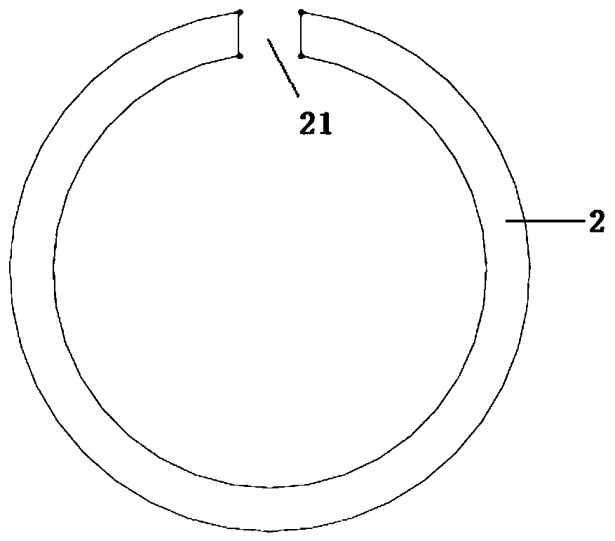
[0027] The above system uses SLA 3D printing equipment improved by self-propagating polymer waveguide technology to print the spherical shell 2, and the top of the spherical shell 2 has an opening 21, such as figure 2 , forming a preceramic polymer struc...
Embodiment 2
[0033] Embodiment 2 (spherical fuel element, no fuel shell is Hastelloy C-276 (00Cr16Mo16W4))
[0034] Computer-aided software (such as Pro / Engineering, Unigraphics, CATIA, Solidworks, etc.) designs the 3D model of the fuel-free shell, then slices and layers (using Magics, Mimics, etc.), and imports the outline into the 3D printing device.
[0035] Using the current mainstream powder making technology, such as the new generation plasma rotating electrode atomization powder making technology (N-PREP), the crucible-free electrode induction melting gas atomization powder making technology (EIGA), the plasma torch atomization powder making technology One is to prepare Hastelloy C-276 powder with an average particle size of about 50 microns.
[0036] The hastelloy C-276 powder is printed with SLM's 3D printing equipment to form a spherical shell with an opening at the top to form a fuel-free shell mold.
[0037] Use a mechanical mixer to uniformly mix graphite powder, binder pheno...
PUM
Abstract
The invention relates to a fuel element preparation method. The method includes steps: providing 3D printing raw materials which include ceramic and / or metal; using the 3D printing raw materials for printing a spherical shell by 3D printing equipment, wherein the top end of the spherical shell is provided with an opening to provide a fuel-free outer shell mould; providing a base material, and adding fuel particles and the base material into the fuel-free outer shell mould to obtain a fuel preform; using the 3D printing raw materials for sealing the opening of the spherical shell of the fuel perform to obtain a fuel formed part; subjecting the fuel formed part to heat treatment to obtain a fuel element, wherein the fuel element comprises a fuel area formed by mixing of the fuel particles and the base material and a fuel-free outer shell formed by the 3D printing raw materials. By the 3D printing forming technique for preparing the fuel element, technical simplicity and high forming speed are realized, the raw material utilization rate is increased, and fuel element preparation cost is sharply reduced.
Description
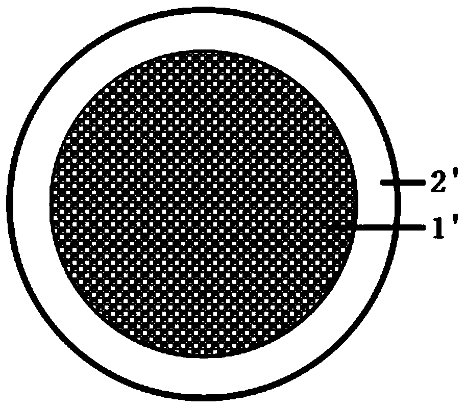
technical field [0001] The invention relates to a molten salt reactor, and more particularly relates to a method for preparing a fuel element. Background technique [0002] Molten salt reactor is one of the six candidate reactor types for fourth-generation nuclear power. It has the advantages of water-free cooling, high-temperature output, normal pressure operation, high energy density and good thermal stability, and is suitable for water-scarce and arid regions. Solid fuel molten salt reactor is a new conceptual design of molten salt reactor, which can give full play to the advantages of traditional coated granular fuel and traditional MSR high temperature molten salt. The fuel element in the reactor is called molten salt reactor fuel element. Its structure Such as figure 1 As shown, the molten salt reactor fuel element is a clad structure, including a fuel zone 1' and a fuel-free shell 2', wherein the fuel zone 1' is formed by mixing clad fuel particles and matrix materia...
Claims
Application Information
Patent Timeline
Application Date:The date an application was filed.
Publication Date:The date a patent or application was officially published.
First Publication Date:The earliest publication date of a patent with the same application number.
Issue Date:Publication date of the patent grant document.
PCT Entry Date:The Entry date of PCT National Phase.
Estimated Expiry Date:The statutory expiry date of a patent right according to the Patent Law, and it is the longest term of protection that the patent right can achieve without the termination of the patent right due to other reasons(Term extension factor has been taken into account ).
Invalid Date:Actual expiry date is based on effective date or publication date of legal transaction data of invalid patent.
Patent Type & AuthorityPatents(China)
IPC IPC(8): G21C21/02
CPCG21C21/02Y02E30/30
Inventor仲亚娟林俊王浩然朱智勇
OwnerSHANGHAI INST OF APPLIED PHYSICS - CHINESE ACAD OF SCI

