
Electric logistics vehicle

A logistics vehicle and electric technology, which is applied in the direction of electric power devices, power devices, vehicle components, etc., can solve the problems of high center of gravity, large chassis space occupation, etc.

Pending Publication Date: 2019-02-22
苏州安耐驰汽车科技有限公司
View PDF0 Cites 10 Cited by
  • Summary
  • Abstract
  • Description
  • Claims
  • Application Information

AI Technical Summary

Problems solved by technology

[0005] At present, the power drive system of the existing pure electric logistics vehicles with front front drive is all set on the frame chassis, specifically on the sub-frame. The sub-frame has the functions of placing the power drive system and connecting the front suspension. The structure of the existing sub-frame is the same as that of a gasoline vehicle, and there is no special structure, which makes the chassis space of the frame after the power drive system is placed takes up a lot and the center of gravity is relatively high

Method used


Image

  • Electric logistics vehicle
  • Electric logistics vehicle
  • Electric logistics vehicle

Examples


Embodiment 1

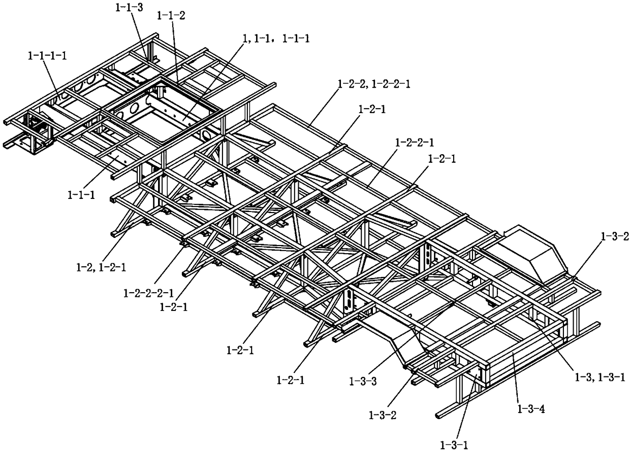
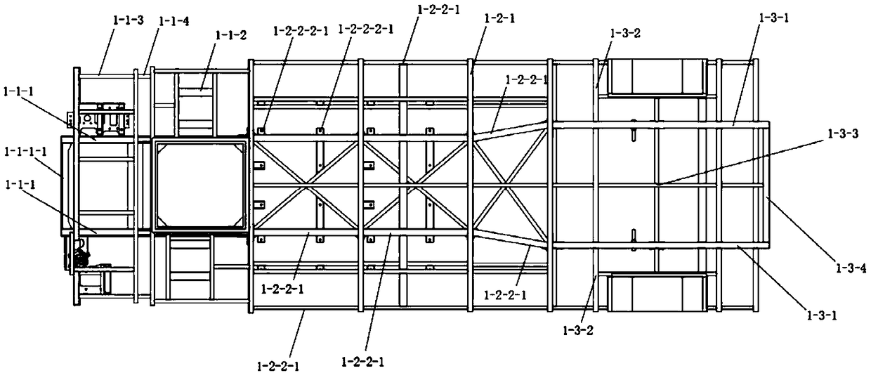
[0099] See Figure 1 to Figure 7 , The electric logistics vehicle of this embodiment includes a chassis 1, a power drive system 2, a subframe 3, a sunken rear axle 4 and a truck body 5. The chassis 1 includes a front bearing part 1-1, a middle bearing part 1-2 and a rear bearing part 1-3. The auxiliary frame 3 and the sunken rear axle 4 are installed on the front bearing part 1-1 and the rear bearing part 1-3 respectively. The power drive system 2 is arranged on the auxiliary frame 3 . The truck body 5 is installed on the chassis 1 .

[0100] The middle bearing part 1-2 of the chassis 1 includes a load-bearing frame 1-2-1 and a middle connecting rod assembly 1-2-2. There are multiple middle connecting rod assemblies 1-2-2, multiple load-bearing frames 1-2-1 are arranged side by side, and a middle connecting rod assembly 1 is passed between every two adjacent load-bearing frames 1-2-1 -2-2 connections. A storage space is formed between every two adjacent bearing frames 1-2...

Embodiment 2

[0139] This embodiment is basically the same as Embodiment 1, except that: the speed ratio of the first input gear set and the speed ratio of the second input gear set of the transmission mechanism 2 - 3 of the power drive system 2 are the same.

Embodiment 3

[0141] This embodiment is basically the same as Embodiment 1, the difference is:

[0142] See Figure 8and Figure 9 . It also includes a truck body 5 installed on the chassis 1 . The truck body 5 includes a compartment frame, a compartment panel 5-1, a compartment door 5-2 and a chassis compartment door 5-3. The compartment panel 5-1 is laid on the compartment frame. The compartment frame includes a front wall frame 5-4, a rear wall frame 5-5, a roof frame 5-6, a side wall frame 5-7 and a connector 5-8. Both ends of the roof frame 5-6 are connected to the front frame 5-4 and the rear frame 5-5. There are two side frame frames 5-7, and the two side frame frames 5-7 are fixed to both sides of the roof frame frame 5-6 by a plurality of connectors respectively. Edges at both ends of the side frame 5-7 are respectively connected to the front frame 5-4 and the rear frame 5-5. The compartment door 5-2 is located on the back wall frame 5-5. The chassis door 5-3 is arranged on...


PUM


Abstract

The invention discloses an electric logistics vehicle comprising a chassis, a power driving system, an auxiliary frame, a sunken type rear axle and a wagon box body. The chassis comprises a front bearing portion, a middle bearing portion and a rear bearing portion; the auxiliary frame and the sunken type rear axle are mounted on the front bearing portion and the rear bearing portion correspondingly; the power driving system is arranged on the front bearing portion and / or the rear bearing portion; and the wagon box body is mounted on the chassis. The electric logistics vehicle is ingenious in structure, the power driving system on the chassis can achieve a front-mounted front-wheel drive, a rear-mounted rear-wheel drive or independent four-wheel-drive manner, the operating efficiency of thedrive system is achieved, and the performance requirements of the vehicle is met.

Description

technical field [0001] The invention relates to an electric logistics vehicle. Background technique [0002] New energy vehicles, especially pure electric logistics vehicles, have developed rapidly in recent years. Today's pure electric logistics vehicle drive system configuration basically adopts a single motor combined with a single gear ratio drive mode. This drive system configuration uses a single reduction ratio and a single drive motor. The speed of the drive motor is in a fixed proportional relationship with the vehicle speed. , using the method of controlling the speed change of the motor to drive the vehicle to change the speed has obvious disadvantages: in order to ensure the dynamic performance of the vehicle, the power margin of the driving motor is large, and the motor is only used for a short time when accelerating or accelerating on a steep slope The problem of peak power reserve at this time is that when the vehicle is running normally, the speed of the dri...

Claims


Application Information

Patent Timeline
Patent Type & Authority Applications(China)
IPC IPC(8): B62D21/00B62D21/11B62D33/04B60K1/02
CPCB62D21/00B60K1/02B62D21/11B62D33/04
Inventor 赖来斌徐明芳路海成
Owner 苏州安耐驰汽车科技有限公司
Learn More