Aerodynamic layout of high-speed aircraft with airframe double-side gas intake

A high-speed aircraft, aerodynamic layout technology, applied in aircraft, fuselage, motor vehicles and other directions, can solve the problems of inability to install radar, landing gear, reduce the practical value of high-speed aircraft, reduce the lift-to-drag ratio of the aircraft, and improve the lift-drag of the aircraft. ratio or adjust the longitudinal stability, improve the heading stability, and improve the effect of lift-drag ratio

Inactive Publication Date: 2019-02-22
BEIJING AEROSPACE TECH INST
View PDF5 Cites 3 Cited by
  • Summary
  • Abstract
  • Description
  • Claims
  • Application Information

AI Technical Summary

Problems solved by technology

The main disadvantages of the aerodynamic layout scheme of this type of aircraft are: (1) For the flat front body, the wave penetration requirements and loading space requirements of the radar cannot be met, and the front body equipped with the radar is usually designed as an axisymmetric or close to axisymmetric profile (2) the inner surface of the lip cover of the air inlet is a high-pressure area, and for the layout scheme of the abdominal air intake, the lip cover high-pressure area produces the effect of negative lift, which reduces the lift-to-drag ratio of the aircraft; (3) the air intake of the abdomen In the layout plan, the flow path of the scram engine is close to the bottom, resulting in asymmetric expansion of the tail nozzle, which may generate negative lift and further reduce the lift-to-drag ratio of the aircraft; poor
The small lift-to-drag ratio of this type of layout leads to a short flight range, and it is impossible to install radar, landing gear, etc., which seriously reduces the practical value of this type of high-speed aircraft
Although the American Manta aircraft adopts a double-side air intake layout scheme, the front body of the aircraft is directly used as the air intake compression surface, which is also relatively flat and poor in practicability

Method used


Image

  • Aerodynamic layout of high-speed aircraft with airframe double-side gas intake
  • Aerodynamic layout of high-speed aircraft with airframe double-side gas intake
  • Aerodynamic layout of high-speed aircraft with airframe double-side gas intake

Examples


Embodiment Construction

[0028] The present invention will be described in further detail below in conjunction with the accompanying drawings.

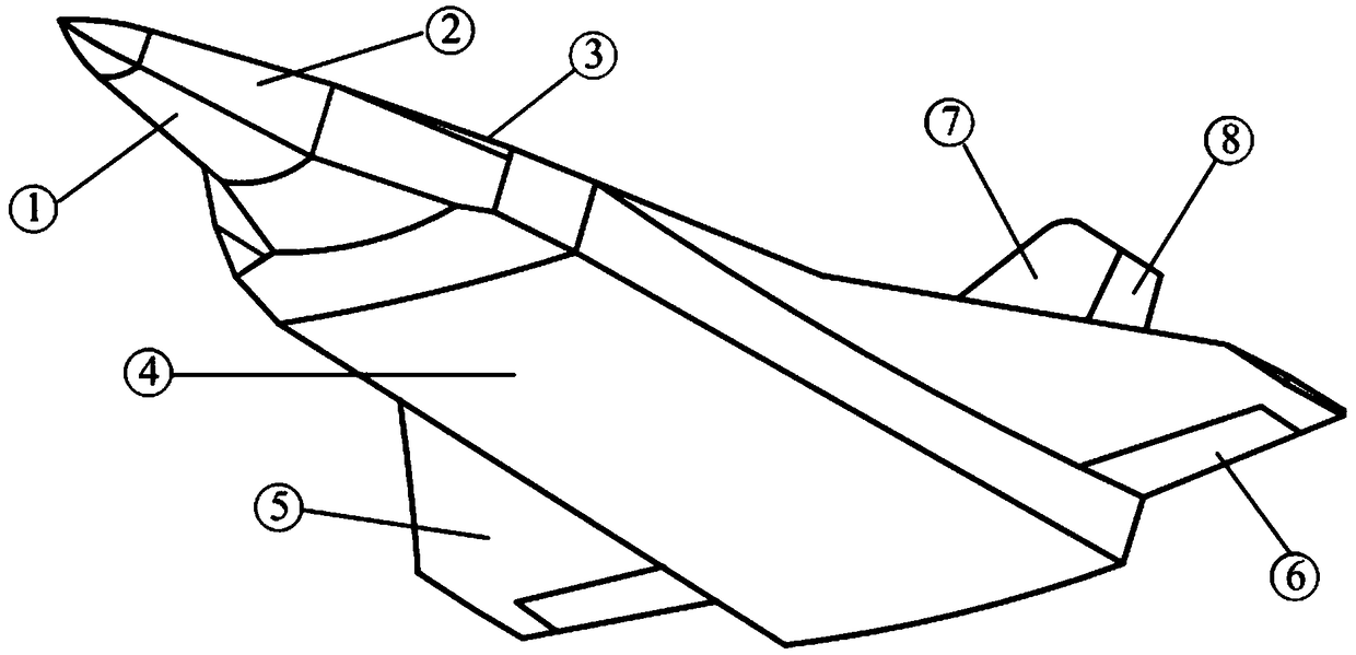
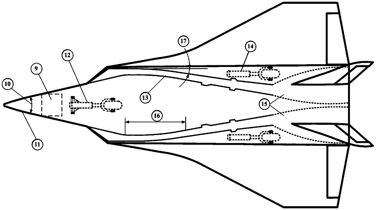
[0029] In a preferred embodiment, the overall length of the aircraft is 25000-30000mm. The two sides of the aircraft head profile are mainly used as the air inlet compression surfaces. According to the field of view of the radar 9 and the requirement of sufficient head loading space, the aircraft head, namely the front body 1, is designed as an axisymmetric cone.

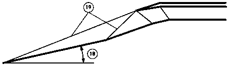
[0030] Install inlet ducts 2 on both sides of the precursor 1, the installation angle 20 is selected from 150° to 180°, and the inlet duct 2 adopts binary compression inlet ducts, according to the principle of "compression shock wave system 19 seals" The binary inlet profile design is carried out based on the oblique shock wave theoretical relation. The input conditions are: the capture area determined according to the overall performance index, the Mach number and the attack angle in the cruising...


PUM

PropertyMeasurementUnit
Full lengthaaaaaaaaaa
Heightaaaaaaaaaa
Widthaaaaaaaaaa

Abstract

The invention provides an aerodynamic layout structure of a high-speed aircraft. A precursor (1), namely, the head of the aircraft, is designed to be an axisymmetric corpus vertebrae. Gas inlets (2) are arranged on two sides of the precursor (1). The installation included angle (19) is selected to be 150-180 degrees. Binary compression gas inlets are adopted as the gas inlets (2). A binary gas inlet profile is designed by using an oblique shock wave theoretical relation according to the principle of "sealing a compression shock wave system (18)". A radar of the aerodynamic layout structure isgood in wave transmission performance and sufficient in installation space, and the lift-to-drag ratio of the aircraft is improved.

Description

technical field [0001] The invention belongs to the technical field of aircraft aerodynamic layout design, and in particular relates to an aerodynamic layout structure of a high-speed aircraft with intake air on both sides of the fuselage. Background technique [0002] Since the concept of high-speed flight was proposed in the 1950s, many countries have carried out research on air-breathing high-speed technology with high-speed weapons as the application target. After decades of hard work, major breakthroughs have been made in scramjet and air-breathing high-speed aircraft technologies. However, the current air-breathing high-speed aircraft is more for the purpose of technical verification, and less practical considerations. Take the X-43 and X-51 aircraft in the United States as examples. In order to ensure the performance of the scramjet engine, the aerodynamic layout scheme of the abdominal air intake is adopted, and the front body of the aircraft is particularly flat. ...

Claims


Application Information

Patent Timeline
IPC IPC(8): B64D33/00B64C1/00B64C3/00B64C30/00
CPCB64C1/0009B64C3/00B64C30/00B64D33/00B64D2033/026
Inventor 王磊汤继斌赵凌波王立宁
Owner BEIJING AEROSPACE TECH INST
Why Eureka
Try Eureka