
Quick self-locking device and shaft system

A self-locking device and fast technology, applied in the field of mechanical transmission, can solve problems such as low efficiency, high assembly precision requirements, and low fault tolerance rate

Pending Publication Date: 2019-02-22
深圳市怀特自动化设备有限公司
View PDF0 Cites 0 Cited by
  • Summary
  • Abstract
  • Description
  • Claims
  • Application Information

AI Technical Summary

Problems solved by technology

In the existing structure, the positioning accuracy of the winding shaft is insufficient, resulting in a low flatness of the end face of the finished product, and the insufficient flatness affects the product quality
At the same time, the positioning and locking mechanism of the rewinding shaft is complex, requiring high assembly precision, and the fault tolerance rate is low, which poses a large safety hazard
In addition, the complex locking structure will also cause cumbersome loading and unloading operations of the winding shaft, which is time-consuming, laborious and inefficient

Method used


Image

  • Quick self-locking device and shaft system
  • Quick self-locking device and shaft system
  • Quick self-locking device and shaft system

Examples


Embodiment 1

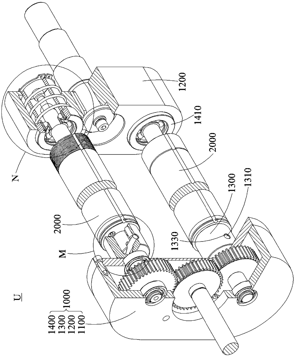
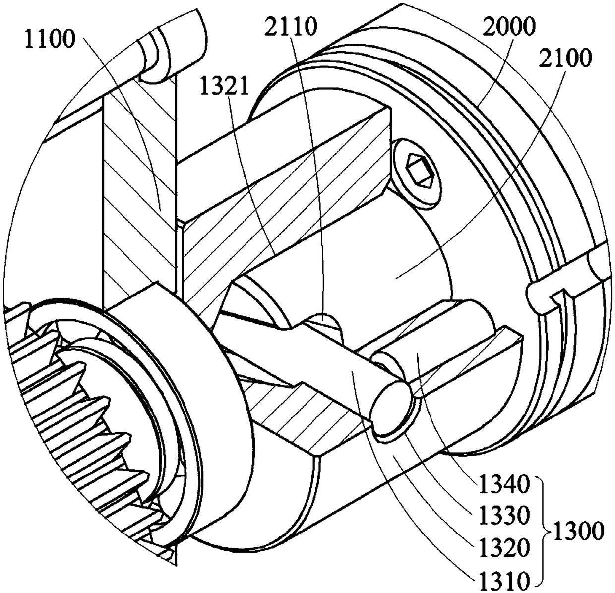
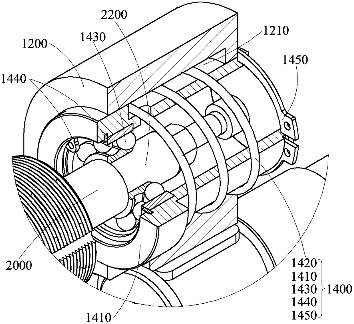
[0033] Please refer to Figure 1~4 , this embodiment discloses a quick self-locking device 1000, including a first support end 1100, a circumferential locator 1300, a second support end 1200 and an axial locator 1400, to realize automatic positioning and locking of the working shaft 2000 with a simplified structure , to ensure positioning accuracy and structural safety, and to compress loading and unloading time to improve production efficiency.

[0034] The first supporting end 1100 and the second supporting end 1200 are located at two ends of the working shaft 2000 for providing end support for the working shaft 2000 . It can be understood that the first supporting end 1100 and the second supporting end 1200 are connected to the frame. It can be understood that the working shaft 2000 is a rotating shaft that rotates to perform a target action, such as a winding shaft, an unwinding shaft, and the like.

[0035] The circumferential positioner 1300 is rotatably held on the fi...

Embodiment 2

[0053] Please refer to Figure 1~4 , this embodiment discloses a fast self-locking shaft system U, including the working shaft 2000 and the fast self-locking device 1000 introduced in Embodiment 1, and realizes the automatic positioning and locking of the working shaft 2000 with a simplified structure, ensuring positioning accuracy and structural safety Sex, and compress loading and unloading time and improve production efficiency.

[0054] Wherein, one end (first shaft end 2100 ) of the working shaft 2000 is positioned on the circumferential positioner 1300 to achieve circumferential positioning; and the other end (second shaft end 2200 ) is positioned on the axial positioner 1400 to achieve axial positioning.


PUM


Abstract

The invention discloses a quick self-locking device comprising a first supporting end, a circumferential positioning device, a second supporting end and an axial positioning device. The first supporting end and the second supporting end are separately arranged at the two ends of a working shaft; the circumferential positioning device is rotatably kept at the first supporting end and is used for achieving circumferential positioning with the working shaft and inputting circumferential rotational motion; and the axial positioning device is axially, elastically and telescopically kept at the second supporting end and used for driving the working shaft to axially abut against the circumferential positioning device for achieving axial positioning. The invention also discloses a quick self-locking shaft system comprising the working shaft and the quick self-locking device. The quick self-locking device and the shaft system realize automatic positioning and locking of the working shaft with asimplified structure, ensure positioning accuracy and product quality by circumferential positioning and axial positioning, simplify the structure to reduce assembly requirements to ensuring structural safety, and are easy to operate so as to improve production efficiency.

Description

technical field [0001] The invention belongs to the technical field of mechanical transmission, and specifically relates to a quick self-locking device and a shaft system. Background technique [0002] Packaging materials are commonly used materials in production and life, commonly including tapes, films, paper and other types. The freshly produced raw coils are relatively soft, and the inside may be damaged or broken. The coil diameter is required and the edge burr is cut out to form a finished coil before leaving the factory for circulation. [0003] Among them, the winding shaft is an indispensable key component. The winding shaft is rotatably held on the frame, and is used to realize the winding of the packaging material in rotation. In the existing structure, the positioning accuracy of the rewinding shaft is insufficient, resulting in low flatness of the end face of the finished product after rewinding, and the insufficient flatness affects the product quality. At ...

Claims


Application Information

Patent Timeline
IPC IPC(8): B65H16/06
CPCB65H16/06B65H2301/41346
Inventor 申亚晨高中明李楠李锐
Owner 深圳市怀特自动化设备有限公司
Learn More