Gear quenching mechanism and gear quenching method
A technology of gear and drive structure, applied in the field of gear processing, can solve the problems of slow heating speed, easy to produce surface deterioration, poor surface hardness of shaft hole, etc., and achieve the effect of fast heating and cooling speed
- Summary
- Abstract
- Description
- Claims
- Application Information
AI Technical Summary
Problems solved by technology
Method used
Image

Examples
Embodiment Construction
[0018] The present invention will be further described below in conjunction with the accompanying drawings and embodiments.
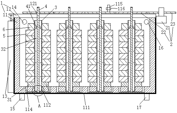
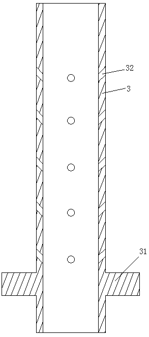
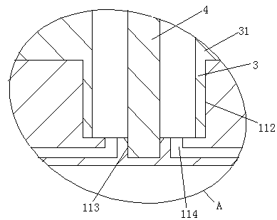
[0019] see figure 1 and figure 2 , a gear quenching mechanism, including a liquid storage tank 1 and a central shaft drive structure 2. The liquid storage tank 1 includes a tank body 11 , a tank cover 12 and an air cylinder 13 for driving the tank cover up and down for opening and closing. The picture of the cylinder block of the cylinder? The two barrels are connected together. The piston rod of the cylinder is connected together with the bung. The outer surface of the bucket body 11 is provided with a thermal insulation layer 111 . The liquid storage barrel is provided with a hot liquid inlet 14 , a hot liquid outlet 15 , a cold liquid outlet 16 and a cold liquid outlet 17 . The bottom wall of the staving is provided with several vertical bearing fixing rods 3 . The bearing fixing rod is a tubular structure. The lower end of the bearing fixing...
PUM
 Abstract
Description
Claims
Application Information
PatSnap Eureka turns technology decisions into work you can execute. Powered by our Innovation Knowledge Graph, it runs expert workflows across engineering, life sciences, materials and intellectual property. Get your review-ready output in minutes.


