
Bond type connector and bond type steel pipe bundle assembly

A technology of connectors and steel tube bundles, applied in the direction of structural elements, building components, building reinforcements, etc., can solve the problems of waste, unreasonable, thick steel bars, etc., and achieve the effect of saving steel and reliable bonding

Inactive Publication Date: 2019-02-22
许仲群
View PDF0 Cites 0 Cited by
  • Summary
  • Abstract
  • Description
  • Claims
  • Application Information

AI Technical Summary

Problems solved by technology

[0002] At present, concrete is poured into the steel pipe bundles as shear walls or columns. The steel pipe bundles are prefabricated in the factory, and the upper and lower steel pipe bundles are connected on the construction site. Since the separating webs of adjacent steel pipes are enclosed inside, the site cannot be directly connected by welding or bolts. , usually using the lap connection of inserting steel bars of equal area, it takes about 90d (d is the diameter of the steel bar) to lap the webs of the upper and lower steel tube bundles, which is very wasteful, and the steel bars are thick and dense, which affects the quality of concrete pouring; because concrete The tensile and shear strength of the joint is only about 2Mpa, which cannot reliably transmit the force of the upper and lower webs, so the strength of the web cannot be utilized for lap joints, which is unreasonable

Method used


Image

  • Bond type connector and bond type steel pipe bundle assembly
  • Bond type connector and bond type steel pipe bundle assembly
  • Bond type connector and bond type steel pipe bundle assembly

Examples


Embodiment 1

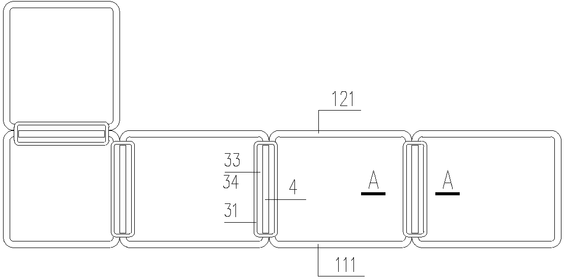
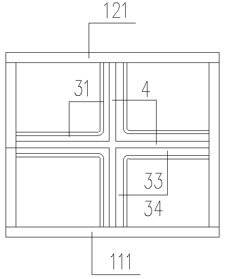
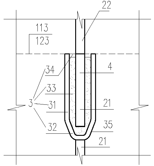
[0024] figure 1 The steel tube bundle shear wall is arranged and connected in sequence with rectangular and plate steel units to form a steel tube with a cavity, which includes the first flange 11, the second flange 12, the web 2, and the web 2 is the adjacent steel tube partition board. Such as image 3 , the webs of the upper and lower steel pipe bundles are connected by bonding, which includes a bag 3, an intermediate piece 4, a lower (steel pipe bundle) web 21, an upper (steel pipe bundle) web 22, and the bag includes closed surrounding sides The wall 31 and the bottom plate 32 are containers with an opening 34 to the top surface of the cavity 33 in the middle; the top surface of the lower web 21 is connected to the bottom surface of the bag, usually by welding, of course, it can also be connected by bolts (the same below); the middle piece 4 is connected to the bottom surface of the upper web 22 (the middle piece 4 can also be an extension of the upper web 22); the cavi...

Embodiment 2

[0035] Such as Figure 4 , U-shaped steel units are arranged in sequence and connected to form a steel tube bundle shear wall. Such as Figure 4 , Figure 5 In the left figure of the left figure, part of the lower web 21 of this example is used as a side wall 37 of the bag 3, and part of the lower first and second flanges 111, 121 are used as the two end side walls 38 of the bag 3; the top of the additional side wall 31 is The inclined surface 36 inclined upwards and outwards can also be a curved surface, and plays the role of guiding the middle piece 4 . Other and embodiment 1 figure 1 , 3 same as the description.

Embodiment 3

[0037] In this example, except that the slope 36 is not established, the arrangement of the bag is the same as that in Embodiment 2. If so Figure 4 The two ends sidewall 38 of bag 1 is provided with grouting hole 5; And as Figure 5The cover 6 shown in the right figure is fixed on the middle piece 4, and can also be fixed on the upper surface of the side wall of the bag 1. The middle piece 4 extends into the cavity, and the cover 6 blocks or tightly closes the opening 34 to prevent concrete from entering; Cover 6 adopts spring sheet, fits better, also can adopt other metal sheet or rubber strip, or spring sheet and rubber strip combination; Then weld connection line 113,123; Then, pour concrete in the cavity of steel pipe bundle; The grout hole 5 is poured with structural glue or other adhesives to fill the cavity 33 and the space under the cover 6 .

[0038] Because the adhesive is welded first and then poured, general adhesives can be used.

[0039] Certainly, embodiment...


PUM


Abstract

The invention relates to a bond type connector and a bond type steel pipe bundle assembly, and belongs to the field of steel structures. The invention provides two technical schemes: (1) the bond typeconnector comprises a bag, a middle piece, a first connected piece and a second connected piece; the bag comprises a sealed peripheral side wall and a bottom plate, and is a container with a middle cavity opened toward the top surface; the first connected piece is connected with the bag; the middle piece is connected with the second connected piece; and the middle piece stretches into the cavityfrom the opening and is adhered tightly by a filled binder; and (2) the bond type steel pipe bundle assembly comprises an upper steel pipe bundle and a lower steel bundle; more than one steel unit isarranged and connected sequentially so as to enclose to form steel pipes with cavities; the upper steel pipe bundle and the lower steel pipe bundle comprise first flanges, second flanges and web; thewebs are separation plates of the adjacent steel pipes; and the webs of the upper steel pipe bundle and the lower steel pipe bundle are connected by adopting the bond type connector. The bond type connector and the bond type steel pipe bundle assembly provided by the invention are beneficial to saving steel materials, simple in structure, convenient to manufacture, and suitable for connecting thesteel pipe bundles at any position.

Description

technical field [0001] The invention belongs to the field of steel structures in the construction industry, and in particular relates to a steel pipe bundle connection. Background technique [0002] At present, concrete is poured into the steel pipe bundles as shear walls or columns. The steel pipe bundles are prefabricated in the factory, and the upper and lower steel pipe bundles are connected on the construction site. Since the separating webs of adjacent steel pipes are enclosed inside, the site cannot be directly connected by welding or bolts. , usually using the lap connection of inserting steel bars of equal area, it takes about 90d (d is the diameter of the steel bar) to lap the webs of the upper and lower steel tube bundles, which is very wasteful, and the steel bars are thick and dense, which affects the quality of concrete pouring; because concrete The tensile and shear strength of the joint is only about 2Mpa, which cannot reliably transmit the force of the upper...

Claims


Application Information

Patent Timeline
IPC IPC(8): E04C5/02E04C5/16E04B2/58
CPCE04C5/02E04B2/58E04C5/163
Inventor 许仲群
Owner 许仲群
Learn More