Composite column of fiber reinforced plastic and machining method of composite column

A technology of fiber-reinforced plastics and processing methods, which is applied in the field of composite columns, can solve the problems of limited improvement in bending resistance, poor radial bending resistance, and low cost of hollow columns, and achieve structural strength and rigidity improvement and strong bending resistance , The effect of improving the connection strength of materials

Pending Publication Date: 2019-02-22
苏州开端机电科技有限公司
View PDF0 Cites 1 Cited by
  • Summary
  • Abstract
  • Description
  • Claims
  • Application Information

AI Technical Summary

Problems solved by technology

At present, conventional profile columns are usually solid or hollow. Solid columns have good structural strength and strong bending resistance, but they have many consumables, heavy weight, and high cost; hollow columns are low in cost and light in weight, but their structural strength is poor. Strengthening ribs are added inside to improve the bending resistance. To enhance the bending resistance, the ribs need to be thickened, and the improvement of the bending resistance is limited.
In addition, the existing FRP or FRP columns have poor radial bending resistance, which limits their scope of use

Method used


Image

  • Composite column of fiber reinforced plastic and machining method of composite column
  • Composite column of fiber reinforced plastic and machining method of composite column
  • Composite column of fiber reinforced plastic and machining method of composite column

Examples


Embodiment Construction

[0033] Below, the substantive features and advantages of the present invention will be further described in conjunction with examples, but the present invention is not limited to the listed examples.

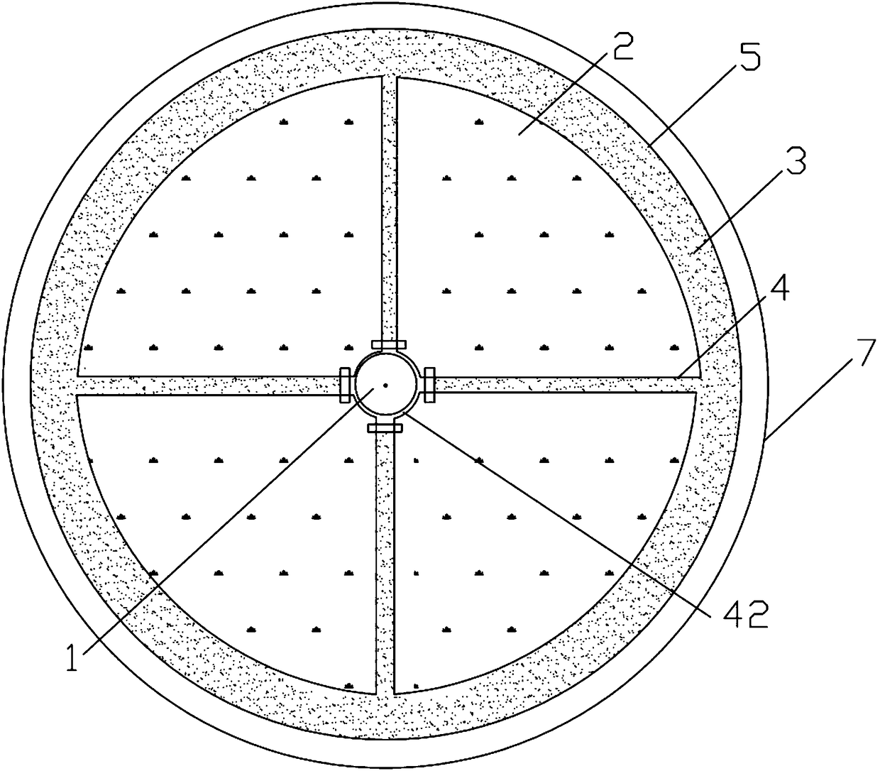
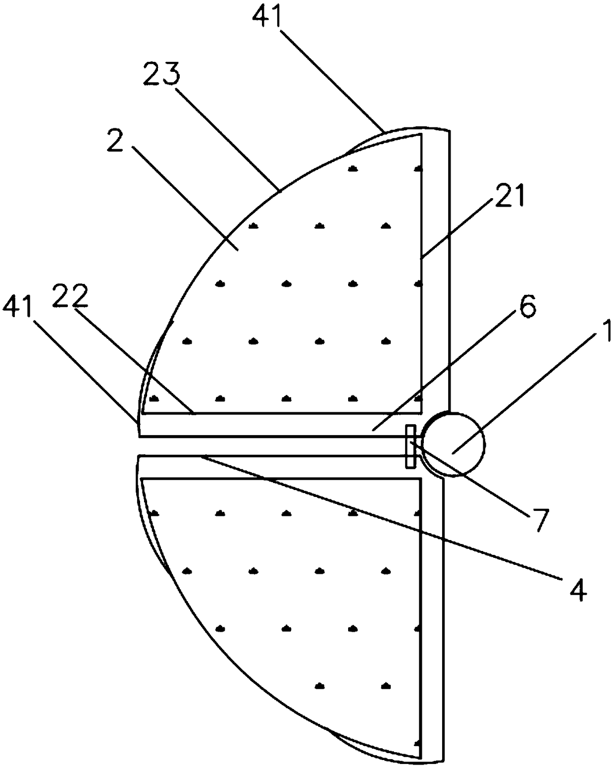
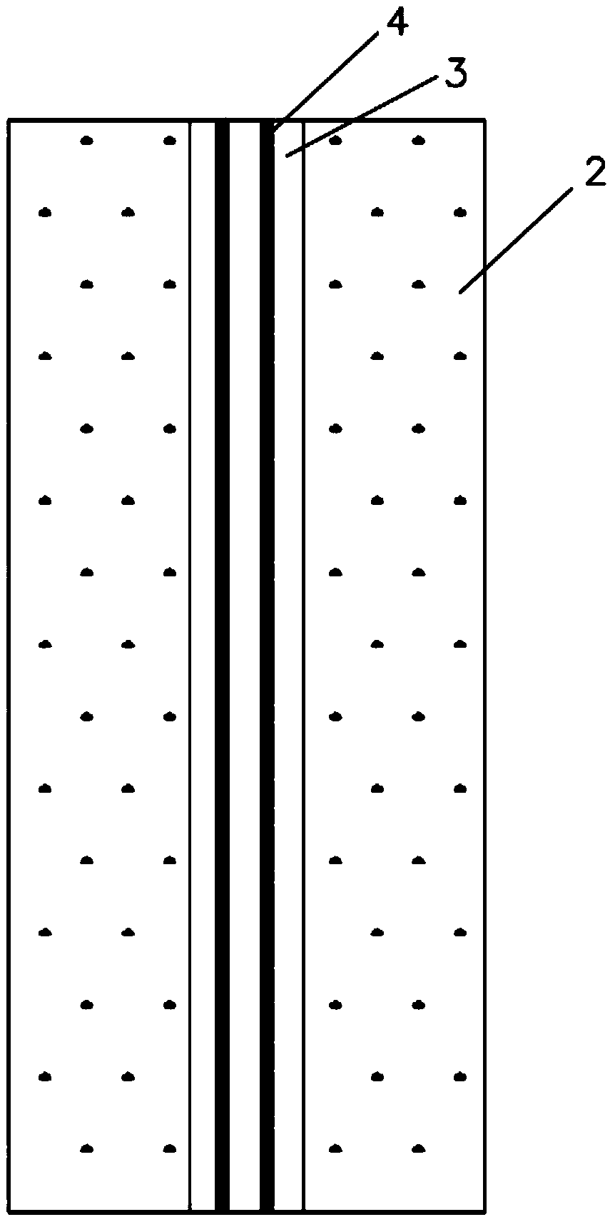
[0034] Such as Figure 1 to Figure 4 As shown, a fiber-reinforced plastic composite column in this embodiment includes a core material 1, a rigid foamed plastic body 2, a resin 3, a reinforcing fiber member 4 and a structural layer 5, and a plurality of rigid foamed plastic bodies 2 surround The core material 1 is arranged at intervals. There are gaps 6 between adjacent rigid foamed plastic bodies 2 , the reinforcing fiber pieces 4 are arranged in the gaps 6 , and the reinforcing fiber pieces 4 are connected to the core material 1 . The structural layer 5 is arranged around the outer side of the rigid foamed plastic body 2 , and the resin 3 is filled in the gap 6 . In the above technical solution, when the composite column receives a radial force, the rigid foamed plastic body...


PUM


Abstract

The invention relates to a composite column of fiber reinforced plastic and a machining method of the composite column. A core material, hard foaming plastic bodies, resin, reinforced fiber pieces anda structural layer are included; the hard foaming plastic bodies encircle the core material and are arranged in a spaced manner; a gap portion is formed between every two adjacent hard foaming plastic bodies; the reinforced fiber pieces are arranged in the gap portions, and extend along the surfaces of the hard foaming plastic bodies in a separating manner and are combined into a whole with the structural layer; the reinforced fiber pieces are connected with the core material; the structural layer is arranged on the outer side of the hard foaming plastic bodies in an encircling manner; and the gap portions are filled with the resin. According to the composite column of the fiber reinforced plastic and the machining method of the composite column, the thickness of the structural layer andthe reinforced fiber pieces can be reduced, and materials are saved; the bending resisting capacity is high, and the corrosion resisting capacity is high; the application range can be widened, and thecomposite column can apply to sea engineering equipment such as a deep sea net box; the manufacturing cost is low; extra floating force can be provided, the specific gravity is small, the same bending resisting strength is achieved, and a traditional metal column is larger in thickness; and the whole weight is small, the specific gravity is small, and the composite column can be used as a floating body.

Description

technical field [0001] The invention relates to the technical field of composite columns, in particular to a fiber-reinforced plastic composite column and a processing method thereof. Background technique [0002] Composite columns are cylindrical parts made of composite materials, which can be used for structural support, such as offshore platforms and deep sea cages. At present, conventional profile columns are usually solid or hollow. Solid columns have good structural strength and strong bending resistance, but they have many consumables, heavy weight, and high cost; hollow columns are low in cost and light in weight, but their structural strength is poor. Strengthening ribs are added inside to improve the bending resistance. To enhance the bending resistance, the ribs need to be thickened, and the improvement of the bending resistance is limited. In addition, the existing fiberglass steel pipes or fiberglass columns have poor radial bending resistance, which limits the...

Claims


Application Information

Patent Timeline
IPC IPC(8): F16S3/00
CPCF16S3/00
Inventor 金伟
Owner 苏州开端机电科技有限公司
Why Eureka
Try Eureka