
direct heat burner

A furnace head and direct heating technology, which is applied in the field of induction cooker, can solve the problems of multi-head furnace waste, inconvenience, and limitation of induction cooker, and achieve the effects of cost reduction, rapid temperature control and energy efficiency improvement

Active Publication Date: 2020-03-20
广东顺德晶纬玻璃制品有限公司
View PDF8 Cites 0 Cited by
  • Summary
  • Abstract
  • Description
  • Claims
  • Application Information

AI Technical Summary

Problems solved by technology

Most traditional induction cookers can only heat metal pots through heating coils, which greatly limits the choice of pots for induction cookers
[0003] In addition, traditional multi-burner stoves are often used in restaurant kitchens. The induction cookers in these restaurant kitchens often contain more than three burners in one multi-head stove, so that each induction cooker can heat more than three small pots at the same time. But when there is no small pot such as casserole to be heated, this multi-burner stove will be idle and cause waste. In addition, in restaurant kitchens, since large pots are often used to stir-fry more dishes at a time, at this time in order to stir-fry The bottom of the large pot is usually round-bottomed, and it is difficult for traditional induction cookers to heat the larger round-bottomed pots in restaurant kitchens, which is inconvenient
In addition, the traditional induction cooker has strong radiation because it adopts an open method. If it is used at a close distance, it may cause a bad influence on users who are close to the distance.

Method used


Image

  • direct heat burner
  • direct heat burner
  • direct heat burner

Examples


Embodiment Construction

[0018] Below in conjunction with embodiment the present invention is further described:

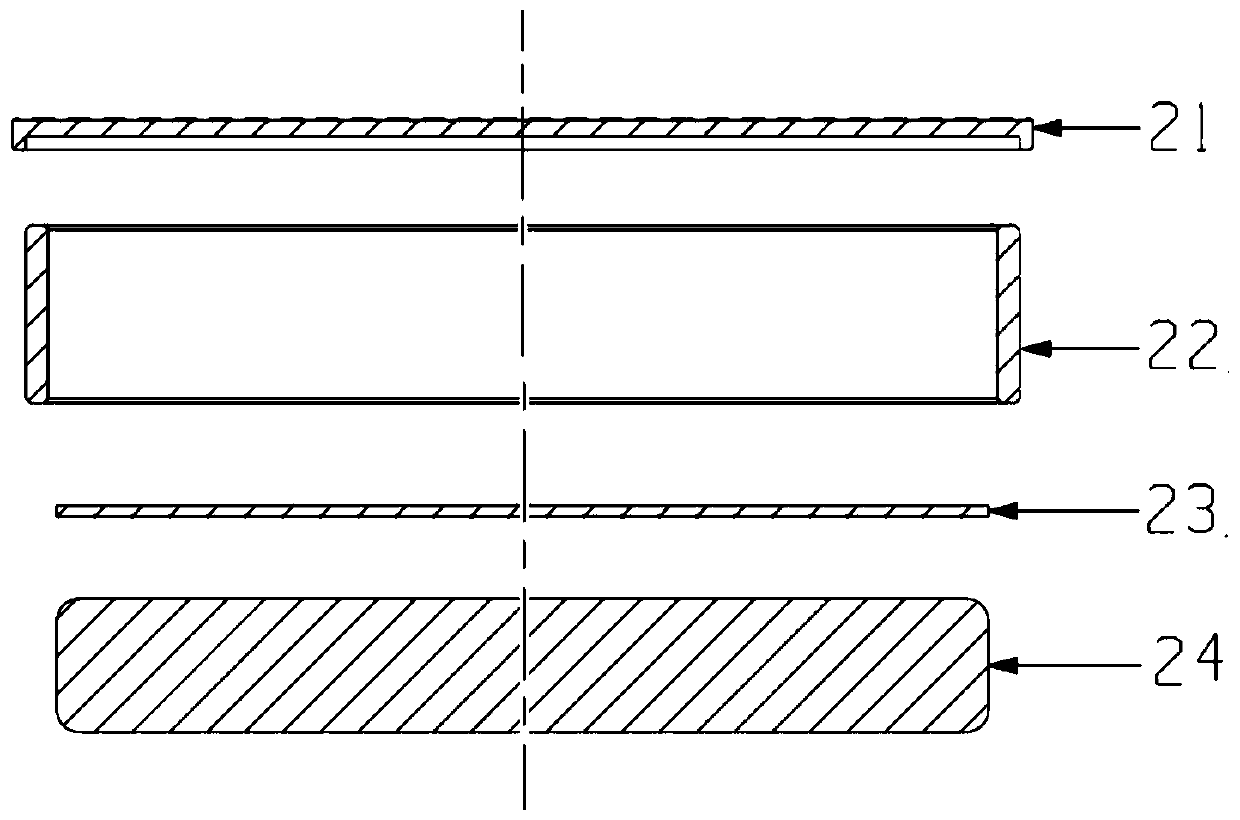
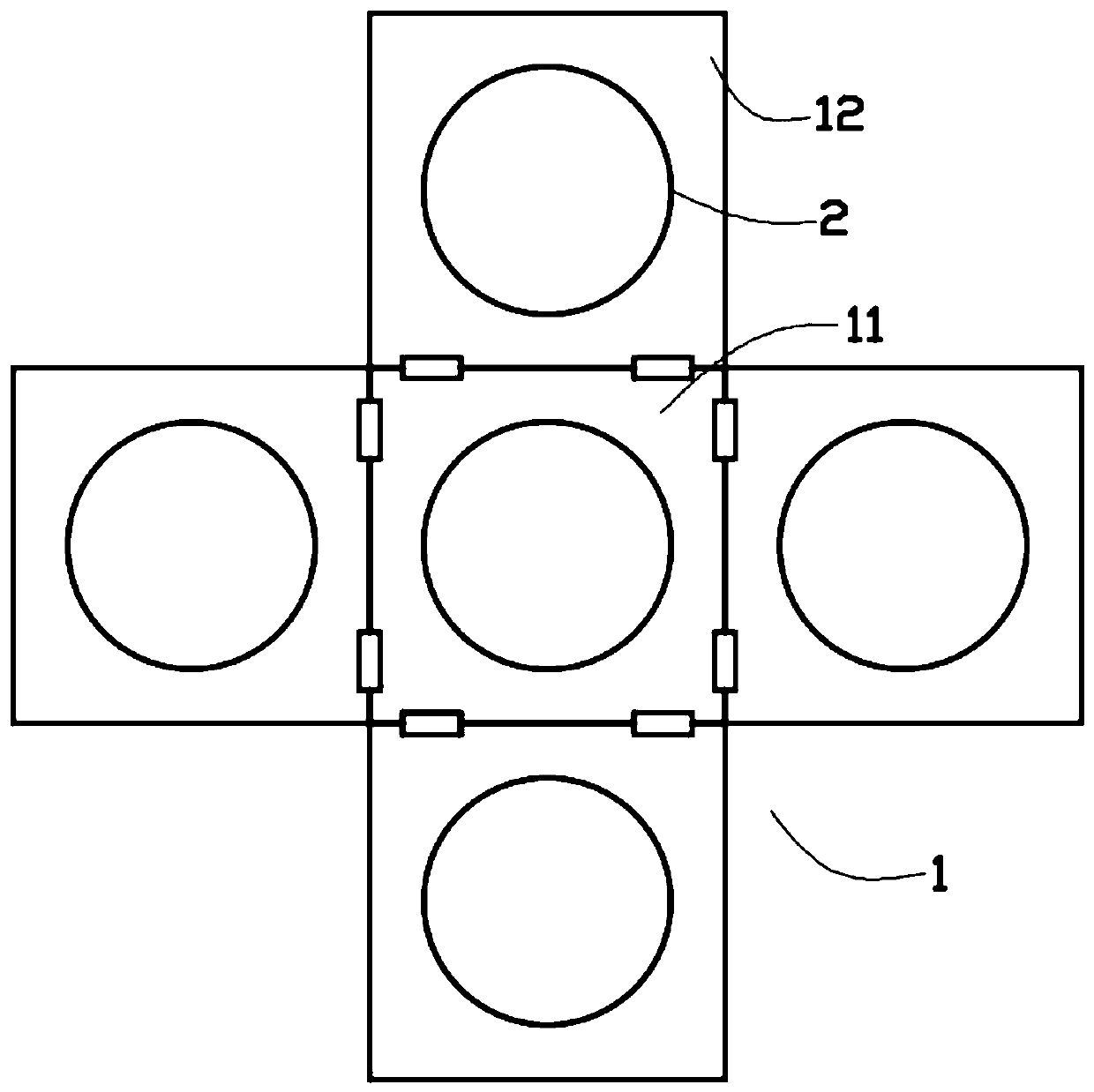
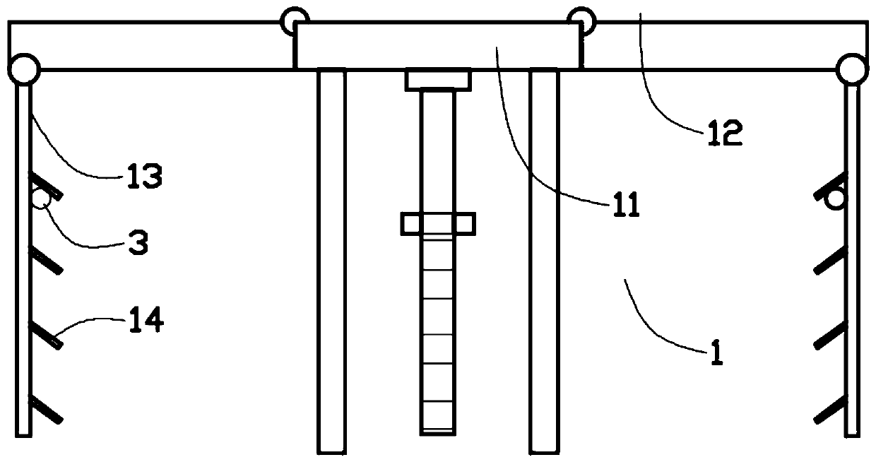
[0019] Such as figure 1 with figure 2 As shown in the embodiment, the direct heating burner includes a furnace base 1 and a burner 2, and the burner 2 includes a heat storage base 21, a protective cover 22, a heat insulation sheet 23, and a heating base 24; the protective cover 22 is designed It is ring-shaped, and the protective cover 22 is made of antimagnetic and waterproof material. The heat storage base 21 is designed as a flat sheet, which is covered and assembled on the upper part of the protective cover 22. The heat storage base 21 is made of metal material, and the heating The base 24 is assembled in the protective cover 22, the inside of the heating base 24 is equipped with a heating coil, the heat insulating sheet 23 is made of heat insulating material, and the heat insulating sheet 23 is sheet-shaped, and the heat insulating sheet 23 It is assembled between the heat storage...


PUM


Abstract

The invention provides a direct heating furnace head. The direct heating furnace head comprises a furnace base and furnace head bodies; each furnace head body comprises a heat storage base, a protecting cover, a heat isolating sheet and a heating base; each protecting cover is designed to be in an annular shape and made of a antimagnetic and waterproof material; each heat storage base is assembledon the upper portion of the corresponding protecting cover in a covering mode; each heating base is assembled in the corresponding protecting cover, and a heating coil is assembled in each heating base; and each heat isolating sheet is made of a heat isolating material, the heat isolating materials can not generate electromagnetic induction, and each heat isolating sheet is assembled between thecorresponding heat storage base and the corresponding heating base. According to the direct heating furnace head, the direct heating furnace head has no requirement on the cooker material when the direct heating furnace head works, the distance between magnetic lines and heating parts can be greatly decreased compared with a traditional electromagnetic furnace, therefore, the energy efficiency ofthe electromagnetic furnace can be significantly improved, alternating electromagnetism of the heating coils can not be emitted to the outside, and higher safety is achieved.

Description

technical field [0001] The invention belongs to the technical field of electromagnetic ovens, and in particular relates to a direct heating oven head. Background technique [0002] Induction cooker has always been an auxiliary tool for kitchen cooking in the Chinese market. Although the induction cooker has the advantages of high thermal efficiency, safety, environmental protection, convenience, and energy saving, it has disadvantages such as difficult control of heating, shaving of pots and utensils, and slow heat replenishment. Therefore, most families use it to boil water and make hot pots. . At present, induction cookers are roughly divided into two types: single-head furnaces and multi-head furnaces. Single-burner stoves are mainly used as kitchen aids in China. The market has shown a rapid decline in the past two years. The main reason is that the technology of induction cookers has not changed substantially over the years. The frequency of use by consumers is relati...

Claims


Application Information

Patent Timeline
Patent Type & Authority Patents(China)
IPC IPC(8): F24C7/00F24C15/00F24C15/08
CPCF24C7/00F24C15/00F24C15/08
Inventor 李敏
Owner 广东顺德晶纬玻璃制品有限公司
Learn More