
Furnace kiln continuous heat exchange control device and control method

A control device and furnace technology, applied in furnace control devices, furnace safety devices, furnaces, etc., can solve the problems of short heat exchange cycle, large fluctuations in furnace temperature and furnace pressure, and achieve less reversal times, improve recovery rate, The effect of improving stability

Inactive Publication Date: 2019-02-22
HUATIAN ENG & TECH CORP MCC +2
View PDF5 Cites 1 Cited by
  • Summary
  • Abstract
  • Description
  • Claims
  • Application Information

AI Technical Summary

Problems solved by technology

[0009] The present invention is made to solve the above-mentioned technical problems, and its purpose is to provide a simplified structure that can solve the problem of large fluctuations in furnace temperature and furnace pressure in regenerative combustion with short heat exchange cycle and frequent heat exchange in the prior art. Problem, continuous heat exchange control device and control method for kilns that can improve the stability of continuous combustion in the regenerator and improve the efficiency of waste heat recovery and utilization

Method used


Image

  • Furnace kiln continuous heat exchange control device and control method
  • Furnace kiln continuous heat exchange control device and control method
  • Furnace kiln continuous heat exchange control device and control method

Examples


Embodiment 1

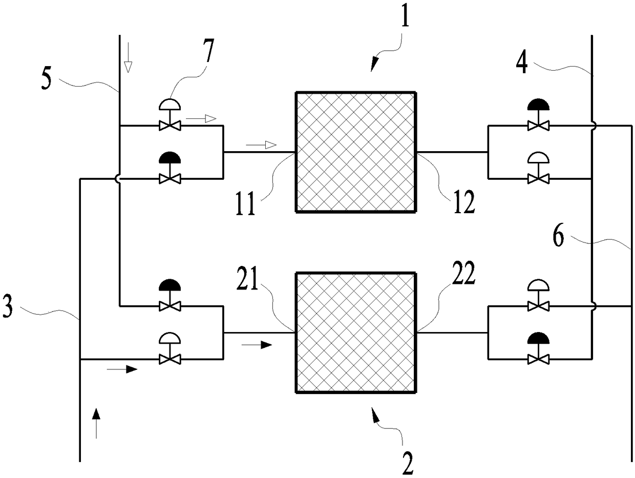
[0020] figure 1 It is a schematic diagram showing the structure of the kiln continuous heat exchange control device described in Embodiment 1 of the present invention. The solid arrows in the figure show the direction of flue gas flow in the device, and the hollow arrows in the figure show the direction of air flow. The direction of flow within the device. Such as figure 1 As shown, the kiln continuous heat exchange control device described in this embodiment of the present invention includes a first heat storage chamber 1, a second heat storage chamber 2, and the first heat storage chamber 1, the second heat storage chamber The flue gas input pipe 3, the flue gas output pipe 4, the air input pipe 5, and the air output pipe 6 communicated with the chamber 2.

[0021] Specifically, the first heat storage chamber 1 includes a first port 11 and a second port 12, and the second heat storage chamber 2 includes a third port 21 and a fourth port 22, see figure 1 , the flue gas inp...

Embodiment 2

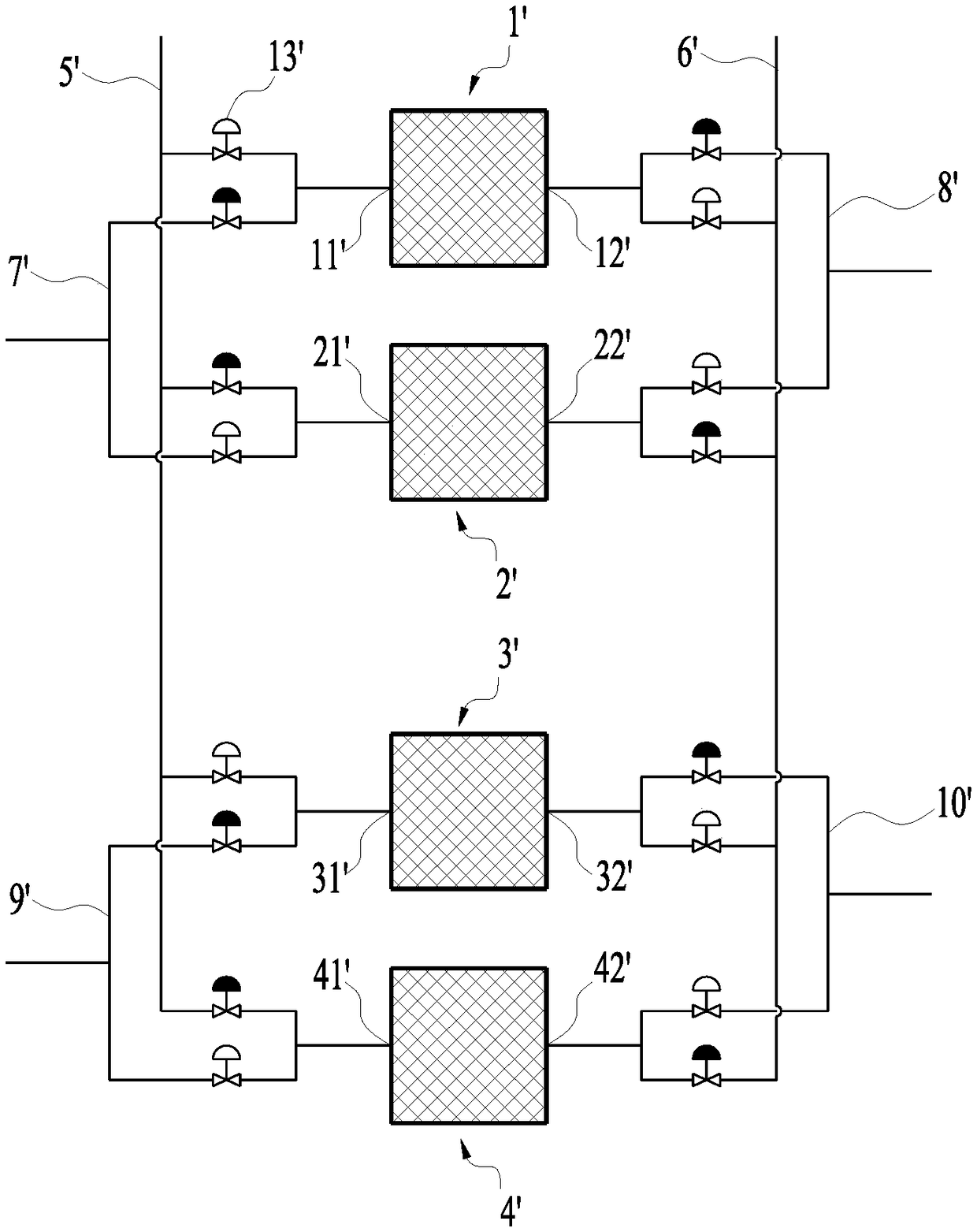
[0024] figure 2It is a schematic diagram showing the structure of the kiln continuous heat exchange control device described in Embodiment 2 of the present invention. Such as figure 2 As shown, the kiln continuous heat exchange control device described in Embodiment 2 of the present invention includes a first regenerator 1', a second regenerator 2', a third regenerator 3' and a fourth regenerator The heat chamber 4', and the flue gas input pipe 5' communicating with the first regenerator 1', the second regenerator 2', the third regenerator 3' and the fourth regenerator 4', and the flue gas output Pipe 6', air input pipe 7', air output pipe 8', gas input pipe 9' and gas output pipe 10'.

[0025] Specifically, the first regenerator 1' includes a first port 11' and a second port 12', the second regenerator 2' includes a third port 21' and a fourth port 22', and the third The regenerator 3' includes a fifth port 31' and a sixth port 32', and the fourth regenerator 4' includes...


PUM


Abstract

The invention provides a furnace kiln continuous heat exchange control device. The device comprises a first heat storage chamber, a second heat storage chamber, a flue gas input pipeline, a flue gas output pipeline, an air input pipeline and an air output pipeline, wherein the flue gas input pipeline, the flue gas output pipeline, the air input pipeline and the air output pipeline are communicatedwith the first heat storage chamber and the second heat storage chamber. Valves are arranged on the pipelines,wherein the pipelines is used for connecting the first heat storage chamber, the second heat storage chamber with the the flue gas input pipeline, the flue gas output pipeline, the air input pipeline and the air output pipeline. The control system controls the valves between the pipelinesand the heat storage chambers to be opened and closed periodically, so that the first heat storage chamber and the second heat storage chamber can be switched periodically between heat absorption andheat release modes. The furnace kiln continuous heat exchange control device and the furnace kiln continuous heat exchange control method have the advantages that the structure and the working process is simple, the problem of short heat exchange period, high furnace temperature and large furnace pressure fluctuation in heat storage combustion caused by frequent heat exchange in the prior art canbe solved, the continuous combustion stability of the heat storage chamber can be improved, and the waste heat recovery efficiency can be improved.

Description

technical field [0001] The invention relates to the technical field of reversing combustion control, in particular to a furnace continuous heat exchange control device and control method. Background technique [0002] Regenerative combustion technology is a technology that burns under high-temperature and low-oxygen air conditions. Usually, the temperature of high-temperature air is greater than 1000°C. Regenerative combustion technology fundamentally improves the energy utilization rate of the heating furnace, especially for low calorific value fuels ( The rational use of blast furnace gas) not only reduces the emission of pollutants (blast furnace gas), but also saves energy. It has become an advanced technology that meets the current resource and environmental requirements, and the adoption of regenerative combustion technology has strengthened Excellent furnace gas circulation, uniform temperature field of the furnace, improved heating quality, and the effect is also ver...

Claims


Application Information

Patent Timeline
Patent Type & Authority Applications(China)
IPC IPC(8): F27D19/00F27D21/00F27D17/00
CPCF27D19/00F27D17/004F27D21/00F27D2017/007F27D2019/0028F27D2021/0057
Inventor 王浩余波吕冬强周炜
Owner HUATIAN ENG & TECH CORP MCC
Learn More