Heat dissipation structure and heat dissipation method for metal fuel cells

A metal fuel cell and heat dissipation structure technology, applied in the direction of fuel cell heat exchange, fuel cells, fuel cell additives, etc., can solve the problems of unsatisfactory heat dissipation effect, high noise, low space utilization rate, etc., and achieve excellent heat dissipation effect, Reasonable structural layout and high space utilization

Pending Publication Date: 2019-02-22
郑州佛光发电设备股份有限公司
View PDF0 Cites 1 Cited by
  • Summary
  • Abstract
  • Description
  • Claims
  • Application Information

AI Technical Summary

Problems solved by technology

[0005] In order to solve the problems of high noise, low space utilization rate and unsatisfactory heat dissipation effect in the existing metal fuel cell heat dissipation scheme, the present invention innovatively provides a metal fuel cell heat dissipation structure and heat dissipation method. The liquid return pipe is used as the return line from the battery reactor to the reaction liquid tank, and the superconducting flat heat pipe and the flat liquid return pipe are bonded together by heat-conducting glue, so as to utilize the strong thermal conductivity of the superconducting flat heat pipe to flow the liquid back into the liquid pipe. Most of the heat of the overheated high-temperature reaction liquid is lost, and part of the heat is lost through the flat liquid return pipe itself. The invention effectively realizes the silent power generation of the metal fuel cell, and has outstanding advantages such as high space utilization rate and good heat dissipation effect.

Method used


Image

  • Heat dissipation structure and heat dissipation method for metal fuel cells
  • Heat dissipation structure and heat dissipation method for metal fuel cells
  • Heat dissipation structure and heat dissipation method for metal fuel cells

Examples


Embodiment 1

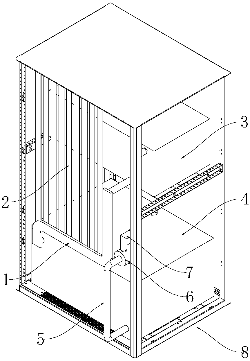
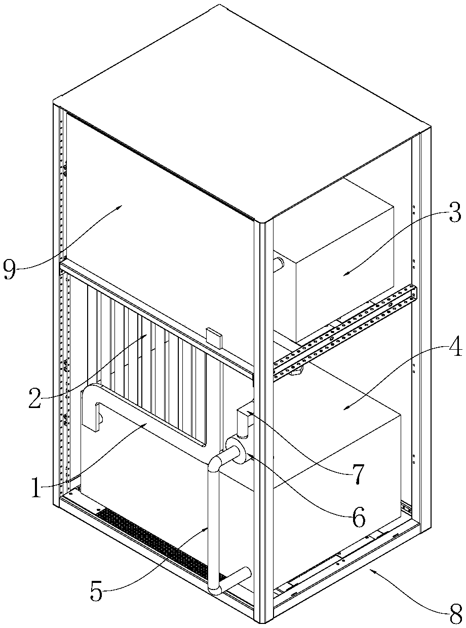
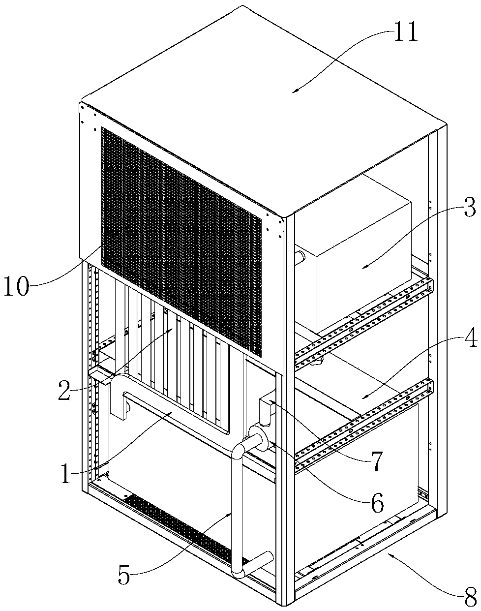
[0045] Such as Figure 1-8 As shown, this embodiment discloses a metal fuel cell heat dissipation structure, and the metal fuel cell involved in the present invention can be an aluminum-air battery, such as figure 1 As shown, the heat dissipation structure includes a flat liquid return pipe 1 and a superconducting flat heat pipe 2. The inlet of the flat liquid return pipe 1 is connected to the liquid outlet of the battery reactor 3, and the outlet of the flat liquid return pipe 1 is connected to the return of the reaction liquid tank 4. The liquid port is connected, and a plurality of superconducting flat heat pipes 2 are bonded to the surface of the flat liquid return pipe 1 through heat-conducting adhesive; Compared with the heat dissipation of the whole reaction liquid box, the present invention only dissipates heat to the liquid flowing through the flat liquid return pipe 1, the heat dissipation effect is better, and the present invention has high reliability, even if one ...

Embodiment 2

[0054] Based on the same inventive concept as Embodiment 1, this embodiment specifically discloses a heat dissipation method for a metal fuel cell. Specifically, the heat dissipation method includes the following steps, such as Figure 8 shown.

[0055] Pumping the reaction solution into the battery reactor 3: under the action of the water pump 6, the reaction solution in the reaction solution tank 4 flows into the battery reactor 3 through the first liquid outlet pipe 5, the water pump 6 and the second liquid outlet pipe 7 in sequence, and reacts The liquid reacts in the battery reactor 3, and in the process of the chemical reaction, heat must be released, and the temperature of the reaction liquid in the battery reactor 3 rises, wherein the battery reactor 3 is arranged above the reaction liquid tank 4;

[0056] Under the action of gravity, the reaction liquid in the battery reactor 3 is led back to the reaction liquid tank 4 through the flat liquid return pipe 1;

[0057] ...


PUM


Abstract

The invention discloses a heat dissipation structure and a heat dissipation method for metal fuel cells. The heat dissipation structure comprises a flat liquid return pipe, superconductive flat heat pipes and a heat dissipation plate, wherein an inlet of the flat liquid return pipe is connected with a liquid outlet of a cell reactor, an outlet of the flat liquid return pipe is connected with a liquid return port of a reaction liquid box, and the multiple superconductive flat heat pipes are bonded to the surface of the flat liquid return pipe; a liquid outlet of the reaction liquid box is connected with a liquid inlet of the cell reactor. The heat dissipation method comprises the steps as follows: a reaction liquid in the reaction liquid box flows into the cell reactor, the reaction liquidin the cell reactor is guided back to the reaction liquid box through the flat liquid return pipe, when the reaction liquid is guided back to the reaction liquid box, heat is dissipated by the superconductive flat heat pipes bonded to the flat liquid return pipe through heat conductive adhesive and the flat liquid return pipe is used for heat dissipation. The heat dissipation structure and the heat dissipation method can significantly improve the heat dissipation effect of the metal fuel cells, thoroughly realize silent power generation of the metal fuel cells and have the outstanding advantages of high space utilization rate, ideal heat dissipation effects and the like.

Description

technical field [0001] The invention relates to the technical field of metal fuel cells, and more specifically, the invention relates to a metal fuel cell heat dissipation structure and heat dissipation method. Background technique [0002] At present, during the working process of metal fuel cells (such as aluminum-air batteries), the reaction of the entire power generation system is an exothermic reaction, so most of the working process of metal fuel cells needs to be cooled. The metal fuel cell cooling scheme adopted in the prior art is: cool down by cooling fans, and the greater the amount of reaction liquid used in the power generation system, the greater the working power of the cooling fans. [0003] However, the heat dissipation fan adopted in the prior art will generate relatively loud noises during operation, and the heat dissipation fan will inevitably occupy additional space, resulting in a low space utilization rate of the existing metal fuel cell power generati...

Claims


Application Information

Patent Timeline
Patent Type & Authority Applications(China)
IPC IPC(8): H01M8/04029H01M8/04007H01M12/06
CPCH01M8/04029H01M8/04067H01M12/06Y02E60/50
Inventor 雷红红张志刚吕涛刘保银王贺省肖建军雷新望易善伟张冬伟李小丽张玉彬郭艳芬
Owner 郑州佛光发电设备股份有限公司
Why Eureka
Try Eureka