Array type capacity coupling radio frequency plasma micro thruster

A radio frequency plasma, capacitive coupling technology, applied in the direction of using plasma, thrust reversers, machines/engines, etc., can solve problems such as weak thrust

Inactive Publication Date: 2019-02-26
SICHUAN UNIV
View PDF2 Cites 11 Cited by
  • Summary
  • Abstract
  • Description
  • Claims
  • Application Information

AI Technical Summary

Problems solved by technology

However, the thrust of the single-tube pocket rocket is too weak, so that

Method used


Image

  • Array type capacity coupling radio frequency plasma micro thruster
  • Array type capacity coupling radio frequency plasma micro thruster

Examples


Embodiment Construction

[0025] The present invention will be further described below in conjunction with the accompanying drawings and specific embodiments.

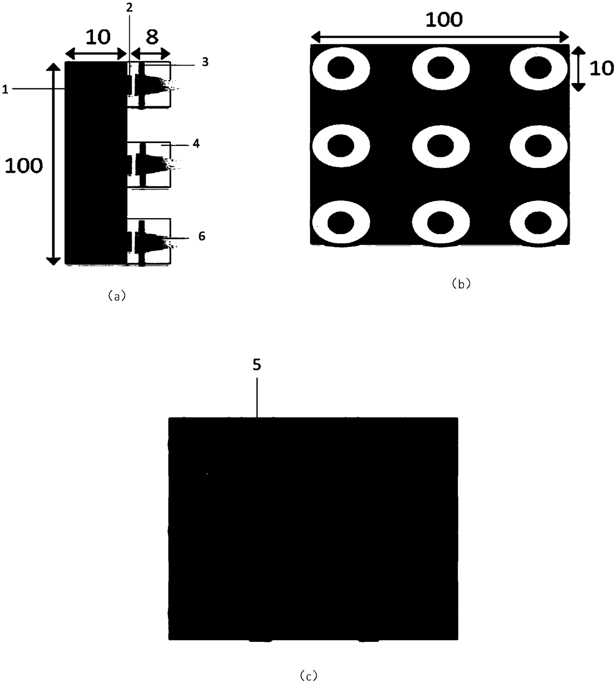
[0026] Array type capacitively coupled radio frequency plasma micro thruster, including gas source, valve, antenna, thrust chamber and power supply.

[0027] in such as figure 1 In the embodiment, a single-sided 3×3 array capacitively coupled radio frequency plasma micro-thruster is used.

[0028] The antenna (3) is wound on the thrust chamber (4). Common plasma antennas such as capacitive coupling antennas, inductive coupling antennas, inductive capacitive coupling antennas, and helical wave antennas can be used for the antennas.

[0029] A valve (2) is used to individually control the switch of each thrust chamber (4).

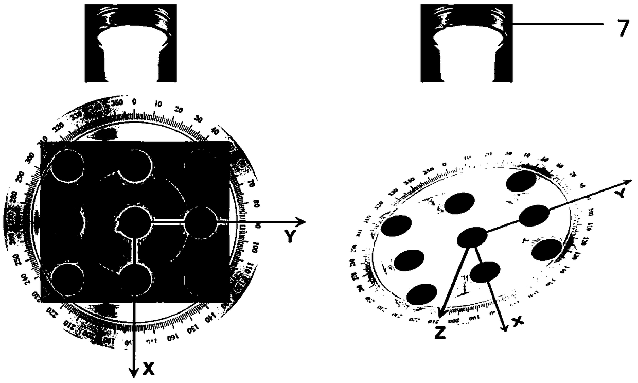
[0030] Place the single-sided array capacitively coupled radio frequency plasma micro-thruster in the vacuum chamber, and evacuate the air pressure to the specified value.

[0031] Gas is introduced from the gas source (1)...


PUM


Abstract

The invention discloses an array type capacity coupling radio frequency plasma micro thruster. The thruster comprises an air source, valves, antennas, thrust chambers and a power supply. The air source is directly connected with the thrust chambers, the valves can control thrust chamber switches respectively, and the antennas wind around the exteriors of the thrust chambers and are connected withthe power supply. The space size and overall quality of a pocket rocket are extremely small, the impulse pulse is low, thrust from micro-newton to millinewton can be achieved, and the average power dissipation is low; meanwhile, precise vector control can be achieved, the thrust is suitable for equipping microsatellites to be used for high precision posture control and position keeping relative totracks.

Description

Technical field: [0001] The present invention is suitable for the field of plasma propulsion technology, that is, a micro-propulsion system with high integration, low power consumption, small thrust, and micro-impulse, and can be applied to micro-satellites (micro-satellites, nano-satellites, pico-satellites) flying in formation and forming constellations, Especially for the design of capacitively coupled radio frequency plasma micro-propulsion (pocket rocket). Background technique: [0002] The propulsion system is a key subsystem for a spacecraft to perform tasks such as orbital maneuvering and special attitude control. However, the microsatellites developed internationally in the past two decades are almost not equipped with propulsion systems, or have only extremely limited maneuverability. The main reason is that the traditional Propulsion systems are large and massive, making them unsuitable for microsatellites. However, with the development of micro-satellite technol...

Claims


Application Information

Patent Timeline
IPC IPC(8): F03H1/00
CPCF03H1/0087
Inventor 苌磊胡馨月
Owner SICHUAN UNIV
Why Eureka
Try Eureka