Heat exchange tube structure capable of eliminating cold shrinkage and thermal expansion damage effects and modularized cooler
A technology of thermal expansion and contraction, heat exchange tubes, applied in the direction of heat exchanger shells, heat exchange equipment, tubular components, etc., can solve the problems of large size, different degrees of thermal expansion and contraction, increase corrugated structure, etc., to reduce production cost effect
- Summary
- Abstract
- Description
- Claims
- Application Information
AI Technical Summary
Problems solved by technology
Method used
Image

Examples
Embodiment 1
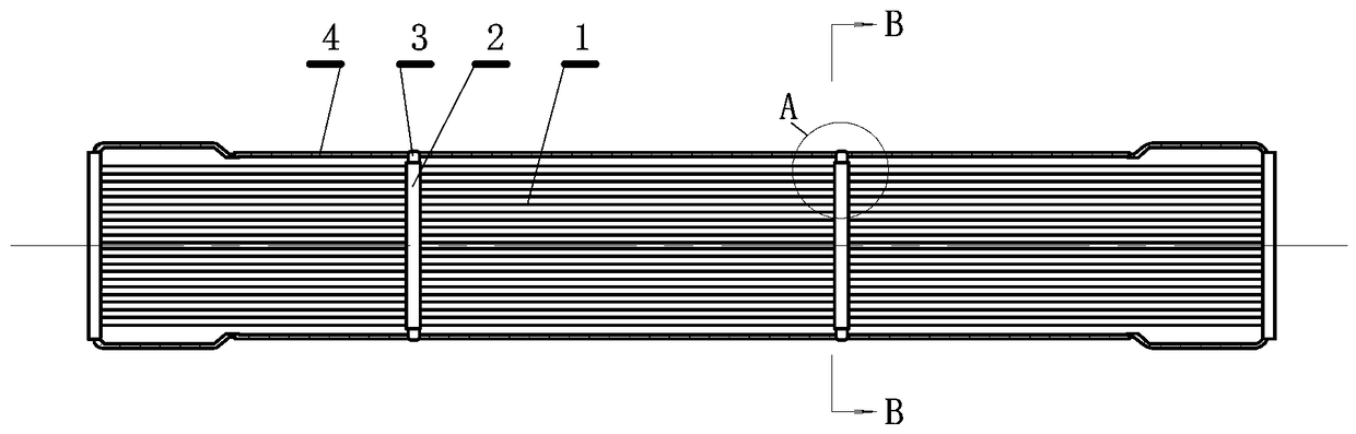
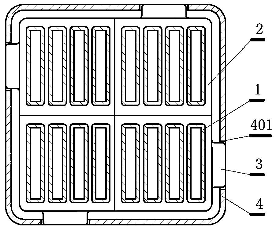
[0027] This embodiment is a heat exchange tube structure that eliminates the damage effect of thermal expansion and contraction, such as figure 1 shown. This embodiment includes: multi-stage heat exchange tube groups 1, each heat exchange tube group is connected by a small tube plate 2, and a plurality of outer edge protrusions 3 are arranged on the periphery of the small tube plate, and the outer edge protrusions are connected to The shell 4 is connected.
[0028] The idea of the heat exchange tube structure in this embodiment to solve the damage effect of thermal expansion and contraction is: divide the long heat exchange tube into several sections, and use small tube sheets for transition in the middle, and the small tube sheets are equivalent to telescopic sections. Displacement occurs in the process of thermal expansion and contraction, and the outer edge protrusions are set on the small tube plate, and the outer edge protrusions are connected with the tube shell to fi...
Embodiment 2
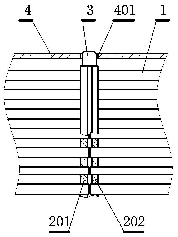
[0034] This embodiment is an improvement of the first embodiment, and is a refinement of the first embodiment with regard to the connection method between the outer edge protrusion and the tube shell. The connection method between the outer edge protrusion and the tube shell described in this embodiment is as follows: a through hole 401 through which the outer edge protrusion can pass is punched on the tube shell, and the outer edge protrusion is inserted into the through hole and welded firmly. Such as figure 2 , 3 shown.
[0035] In this embodiment, a through hole is drilled on the tube shell, so that the outer edge protrusion on the small tube plate is inserted into the through hole and welded firmly. The advantage of this structure is that the process is simple and the welding of the small tube sheet and the tube shell can be carried out outside the tube shell, which is very convenient. At the same time, the welding is firm and can be completely fixed to avoid displacem...
Embodiment 3
[0037] This embodiment is an improvement of the first embodiment, and is a refinement of the first embodiment with regard to the connection method between the outer edge protrusion and the tube shell. The connection method between the outer edge protrusion and the shell in this embodiment is as follows: two short longitudinal ribs 403 and 404 protruding inward are arranged on the shell, and the outer ribs are inserted between the short longitudinal ribs. The protrusion on the outer edge limits the displacement of the protrusion on the outer edge along the long direction of the heat exchange tube, in the direction indicated by the arrow c, such as Figure 4 shown.
[0038] In this embodiment, the protrusion on the outer edge of the small tube sheet is not welded to the shell, but under the restriction of two short longitudinal ribs, the displacement of the small tube sheet is limited to the displacement in the long direction of the heat exchange tube, while the longitudinal dir...
PUM
 Abstract
Description
Claims
Application Information
 - R&D
- Intellectual Property
- Life Sciences
- Materials
- Tech Scout
- Unparalleled Data Quality
- Higher Quality Content
- 60% Fewer Hallucinations
Browse by: Latest US Patents, China's latest patents, Technical Efficacy Thesaurus, Application Domain, Technology Topic, Popular Technical Reports.
© 2025 PatSnap. All rights reserved.Legal|Privacy policy|Modern Slavery Act Transparency Statement|Sitemap|About US| Contact US: help@patsnap.com