Rapid aging method for catalytic gasoline particle catcher

A particle trap and rapid aging technology, applied in the direction of instruments, machine/structural component testing, measuring devices, etc., can solve the problems of high cost, long cycle, different exhaust atmosphere, etc., and achieve strong practicability and easy operation , the effect of short cycle

Active Publication Date: 2019-02-26
昆明贵研催化剂有限责任公司 +1
View PDF5 Cites 10 Cited by
  • Summary
  • Abstract
  • Description
  • Claims
  • Application Information

AI Technical Summary

Problems solved by technology

The actual vehicle durability test studies the durability performance of cGPF, which requires a long cycle and high cost. Although the burner test can quickly realize the rapid accumulation

Method used


Image

  • Rapid aging method for catalytic gasoline particle catcher
  • Rapid aging method for catalytic gasoline particle catcher
  • Rapid aging method for catalytic gasoline particle catcher

Examples


Embodiment 1

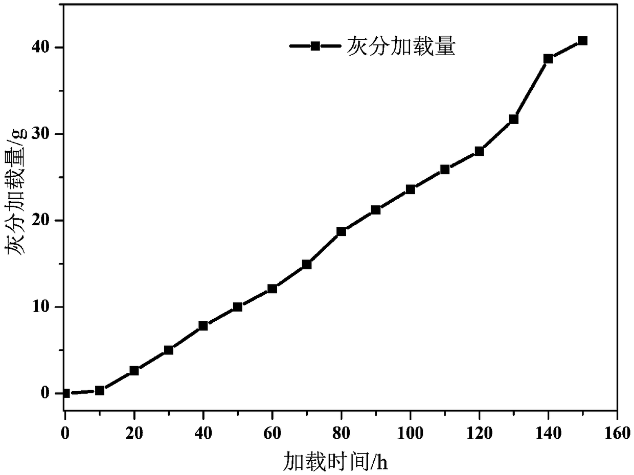
[0024] The carrier specification of the catalytic gasoline particulate filter used in this example is Φ118.4*152.4 (mm), the mesh number is 300cpsi, the wall thickness is 8mil, the volume is 1.68L, and its load is 75g / L catalyst coating, and the precious metal content is 8g / ft 3 . The example target ash load M t It is 42g, simulating the 200,000 endurance mileage of a real car.

[0025] The present invention comprises the following steps:

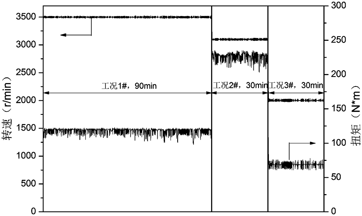
[0026] (1) According to the SRC test data of the 1.5L TGDI vehicle and the engine universal characteristics and emission test data obtained on the 2.0L TGDI engine bench; design three steady-state working conditions (denoted as working condition 1#, working condition 2 #, Working condition 3#) rapid aging, which is characterized by working condition 1# having high fuel consumption rate, working condition 2# having high fuel consumption rate and high exhaust temperature, working condition 3# having high particulate matter and smoke emiss...

Embodiment 2

[0035] The carrier specification of the catalytic gasoline particle filter used in this example is Φ118.4*152.4 (mm), the mesh number is 300cpsi, the wall thickness is 8mil, the volume is 1.68L, and its load is 100g / L catalyst coating, and the precious metal content is 8g / ft 3 . The example target ash load M t It is 33.6g, and the endurance mileage of a simulated real car is 160,000.

[0036] Include the following steps:

[0037] (1) The catalytic gasoline particulate filter is tested on a 1.5LTGDI vehicle, and the vehicle emission test results are used as the test comparison after aging;

[0038] (2) Aging the catalytic gasoline particulate filter after the vehicle test on the 2.0LTGDI engine bench, weighing the catalyst at 200°C before starting the aging, and determining the weight M before aging 0 . Then perform aging according to the selected rapid aging conditions. Rapid aging working condition is made up of three steady-state working conditions (i.e. working condi...


PUM

PropertyMeasurementUnit
Meshaaaaaaaaaa
Volumeaaaaaaaaaa

Abstract

The invention discloses a rapid aging method for a catalytic gasoline particle catcher. The method comprises a step of rapidly aging the catalytic gasoline particle catcher according to a selected rapid aging condition on an engine rig, wherein the rapid aging condition is formed by three steady-state conditions, a step of performing carbon removal and weighing under a carbon removal condition todetermine soot and ash load after 1 to 6 aging cycles, a step of continuing to perform aging if the ash load Mi is smaller than a target ash load Mt, otherwise, stopping a test if Mi is larger than orequal to Mt, and a step of periodically performing performance test on the catalytic gasoline particle catcher in the whole test. The method of the invention has the advantages of easy operation andhigh practicability, the investigation of the loading of ash of the catalytic gasoline particle catcher, the accumulation and regeneration of soot and the durability of the catalyst can be quickly andaccurately realized, the aging and ash accumulation of the catalyst in a real vehicle aging are simulated, and the time of catalyst aging performance evaluation is shortened.

Description

technical field [0001] The invention relates to the field of after-treatment of automobile exhaust gas, in particular to a rapid aging method for a catalytic gasoline particle trap. Background technique [0002] In recent years, air pollution has become an important restrictive factor for urban development and improvement of people's living standards. Strengthening the prevention and control of urban motor vehicle pollution and improving the level of emission control are important measures to improve air quality. In 2016, my country issued the latest emission standards of "Light Vehicle Pollutant Emission Limits and Measurement Methods (China's Sixth Phase)", which tightened the emission limits of gaseous pollutants in the exhaust gas, and carried out the quality and quantity of particulate matter emissions from the engine. After 2020, the limits are 3.0mg / km and 6.0*10 11 # / km. Faced with strict particulate matter emission limits, gasoline particulate filter (GPF) is cons...

Claims


Application Information

Patent Timeline
IPC IPC(8): G01M17/007
CPCG01M17/007
Inventor 夏文正杨冬霞袁新波贺小昆郑毅颜燕冯丰付铁强赵德鹏景晓军
Owner 昆明贵研催化剂有限责任公司
Why Eureka
Try Eureka