

Novel busbar
A busbar, a new type of technology, applied in the installation of busbars, busbar/line layout, electrical components, etc., can solve the problems of poor dynamic stability and thermal stability of rectangular busbars, low carrying capacity of rectangular busbars, and small carrying capacity , to avoid skin effect, reduce skin effect and reduce weight
- Summary
- Abstract
- Description
- Claims
- Application Information
AI Technical Summary
Problems solved by technology
Method used
Image

Examples
Embodiment Construction
[0021] The present invention will be described in further detail below in conjunction with the accompanying drawings and embodiments.
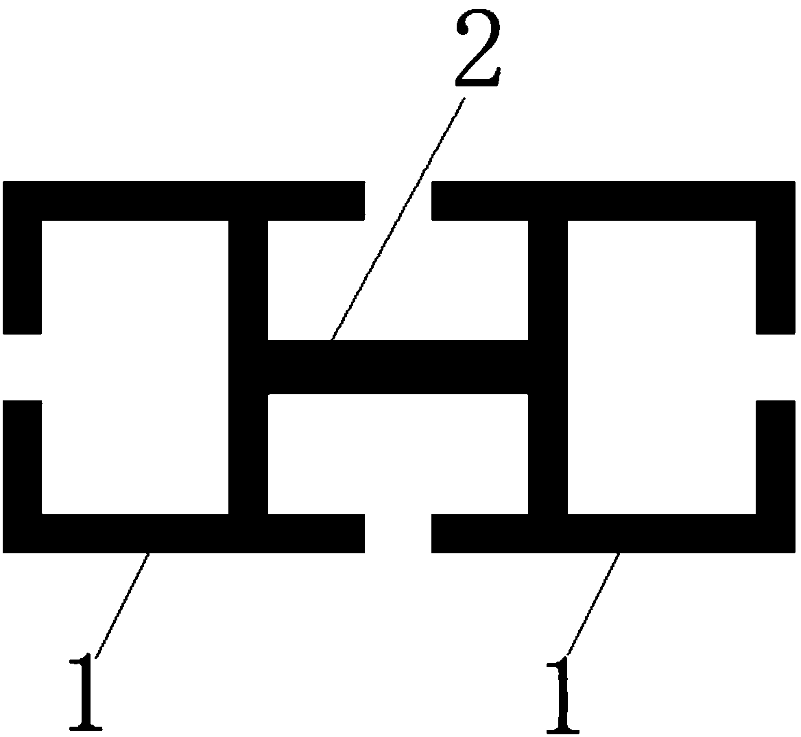
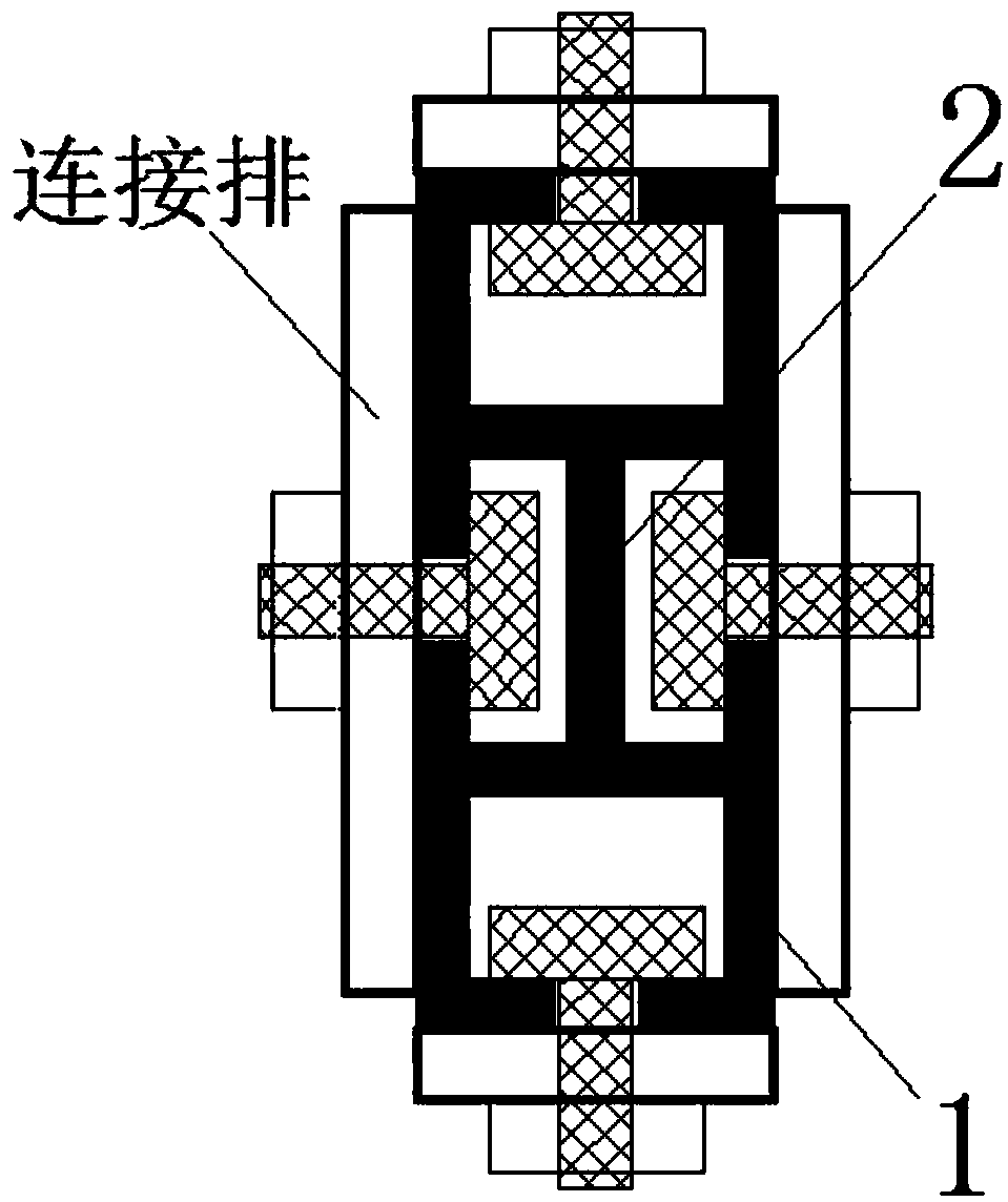
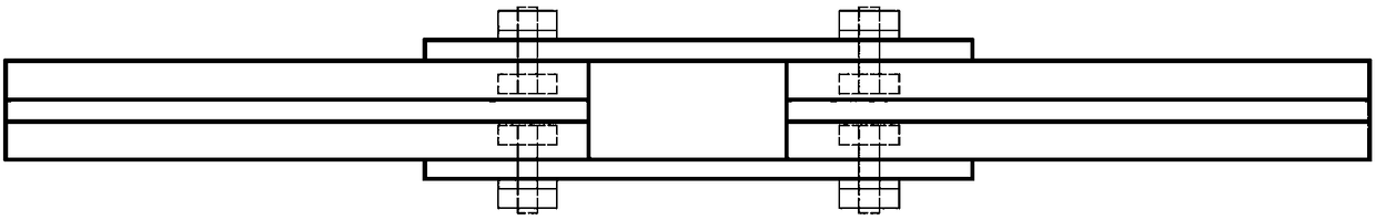
[0022] like Figure 1-3 As shown, a new type of busbar includes two C-shaped busbar main bodies 1, and the two C-shaped busbar main bodies 1 are connected back to back through a connecting plate 2; the connecting plate 2 is perpendicular to the C-shaped busbar main body 1, and its Connect the middle part of two C-shaped busbar main bodies 1; the upper and lower parallel sides of one C-shaped busbar main body 1 extend to the other C-shaped busbar main body 1 but are not connected. This structure makes the busbar form an upward direction The lower two notches, the section length of such notches is shorter than the section length of connecting plate 2.
[0023] like figure 2 As shown, such a busbar looks like 4C, with notches on all four sides, which can realize the connection without holes on all sides. The cap part is in a rectangular shape...
PUM
 Abstract
Description
Claims
Application Information