Hydraulic continuous drawing mechanism and copper alloy wire rod surface peeling system

A copper alloy, hydraulic technology, applied in metal extrusion, metal wire drawing, metal processing equipment and other directions, can solve the problems affecting the peeling effect of disc products, and achieve the effect of simple structure, power drive, and surface quality assurance.

Pending Publication Date: 2019-03-01
YANTAI WANLONG VACUUM METALLURGY
View PDF0 Cites 4 Cited by
  • Summary
  • Abstract
  • Description
  • Claims
  • Application Information

AI Technical Summary

Problems solved by technology

Existing drawing machines can provide power drive, but most of the existing drawing machines are used for straightening and correcting products, so drawing trolleys or pliers are often used to act on the surface of products to be straightened, and only need to be The effect of straightening does not pay attention to the wear on the surface of the product. Although the drawing machine can realize power drive, for the peeled round products, it cannot cause wear and tear to the round products with smooth surface after peeling. Peeling effect of the product

Method used


Image

  • Hydraulic continuous drawing mechanism and copper alloy wire rod surface peeling system
  • Hydraulic continuous drawing mechanism and copper alloy wire rod surface peeling system
  • Hydraulic continuous drawing mechanism and copper alloy wire rod surface peeling system

Examples


Embodiment Construction

[0046] The principles and features of the present invention are described below in conjunction with examples, which are only used to explain the present invention and are not intended to limit the scope of the present invention.

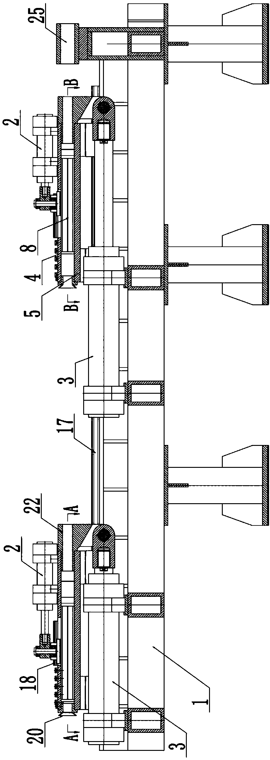
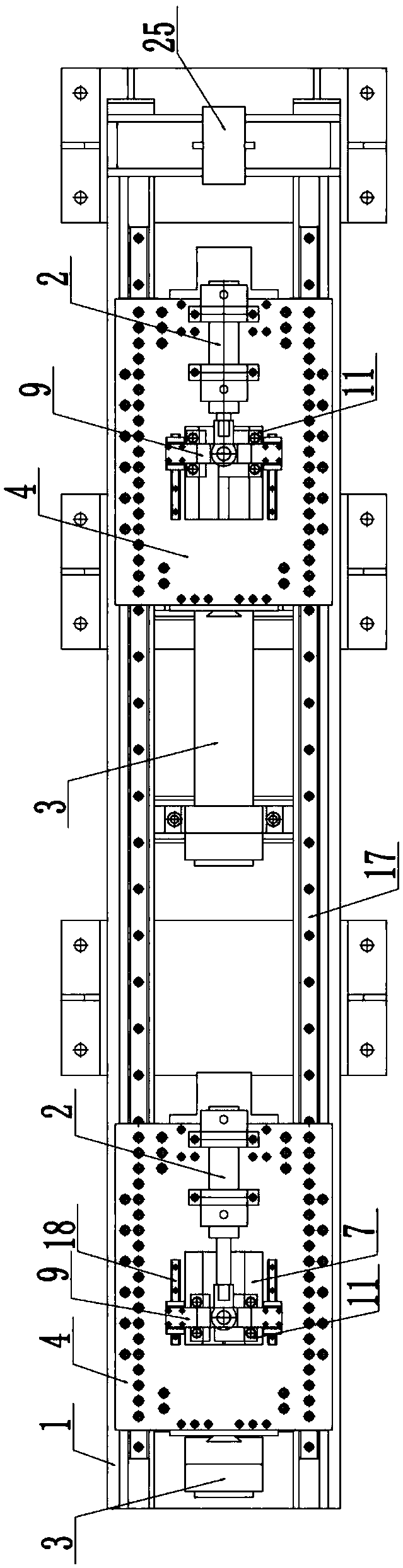
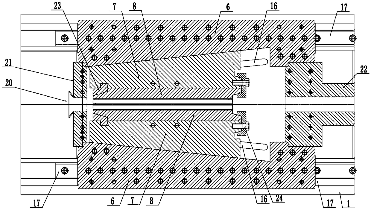
[0047] like Figure 1-Figure 7 As shown, a hydraulic continuous drawing mechanism includes a drawing workbench 1, a front drawing mechanism and a rear drawing mechanism arranged on the drawing workbench 1, and the front and rear drawing mechanisms all include a mobile platform, Large oil cylinder 3 and small oil cylinder 2, the mobile platform moves forward and backward on the drawing workbench under the action of the large oil cylinder, the mobile platform includes a top plate 4, a bottom plate 5, and is located between the top plate and the bottom plate A pair of positioning plates 6, a pair of slide plates 7, and a pair of half-moulds 8, a pair of positioning plates are installed between the top plate and the bottom plate, a pair of positioning pl...


PUM


Abstract

The invention discloses a hydraulic continuous drawing mechanism and a copper alloy wire rod surface peeling system adopting the drawing mechanism. The drawing mechanism comprises a drawing workbench,a front drawing mechanism body and a rear drawing mechanism body. Each drawing mechanism body comprises a moving table, a die, a large oil cylinder and a small oil cylinder, wherein the moving tablemoves forwards and backwards under the action of the large oil cylinder, the moving table comprises a top plate, a bottom plate, a pair of positioning plates, sliding plates and a half die, a movablespace with a narrow front portion and a wide rear portion is formed between the pair of positioning plates, and the sliding plates are arranged on the inner sides of the positioning plates and can move back and forth along the inclined planes of the inner sides of the positioning plates. The peeling system comprises a paying-off mechanism, a vertical roller straightening mechanism, a vertical roller straightening mechanism, a straightening die, a turning peeling machine, the hydraulic continuous drawing mechanism and a take-up mechanism. The concentric or small-amplitude eccentric peeling of awire rod is realized, and the surface is clean and bright; meanwhile, the speeds of the oil cylinders of the hydraulic continuous drawing mechanism are matched to alternately work, the whole wire rodcan be continuously peeled, continuous peeling is achieved, and the production efficiency is high.

Description

technical field [0001] The invention relates to a hydraulic continuous drawing mechanism and a copper alloy disk circular surface peeling system using the drawing mechanism, which belongs to the technical field of copper alloy wire stripping. Background technique [0002] During the production process of the rolled copper alloy disc, the surface of the copper alloy wire will be slightly oxidized and blackened, and the oxide layer will affect the quality of subsequent products. Therefore, it is necessary to peel the surface of the copper alloy disc. At present, the existing peeling equipment mainly includes sandblasting peeling, surface grinding and peeling, pulling and peeling through drawing dies, etc. Although there are many peeling methods, they are not suitable for peeling round products, but suitable for round products. The chemical rinsing method of product surface treatment not only has high production cost and low production efficiency, but also causes environmental ...

Claims


Application Information

Patent Timeline
Patent Type & Authority Applications(China)
IPC IPC(8): B21C1/02B21C19/00B21C43/04B21C47/04
CPCB21C1/02B21C19/00B21C43/04B21C47/04
Inventor 陈德胜董春波林才李秀梅王风德武同伟
Owner YANTAI WANLONG VACUUM METALLURGY
Why Eureka
Try Eureka