
Hydraulic expansion device

A technology of hydraulic pressure and expansion block, which is applied in the direction of positioning device, expanding mandrel, clamping, etc., which can solve the problems of scrapped parts, excessive clamping deformation of thin-walled cylindrical parts, loose processing of thin-walled cylindrical parts, etc.

Inactive Publication Date: 2019-03-01
刘剑
View PDF9 Cites 10 Cited by
  • Summary
  • Abstract
  • Description
  • Claims
  • Application Information

AI Technical Summary

Problems solved by technology

[0002] When processing typical thin-walled cylindrical parts, when the coaxiality between the outer circle and the inner hole is high according to the design requirements, in order to ensure the machining accuracy, a hydraulic expansion device is usually used, but the hydraulic expansion device in the prior art, its The adjustment of the expansion force depends entirely on the experience and feeling of the operator. When processing typical thin-walled cylindrical parts, if the expansion force is too large, the clamping deformation of the thin-walled cylindrical parts will be too large and the parts will be scrapped. , if the expansion force is too small, the thin-walled cylindrical parts will loosen during processing due to insufficient expansion force

Method used


Image

  • Hydraulic expansion device
  • Hydraulic expansion device
  • Hydraulic expansion device

Examples


Embodiment Construction

[0017] The present invention will be further described below in conjunction with the accompanying drawings and given embodiments.

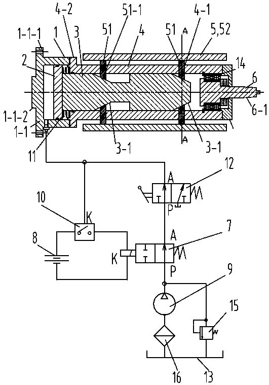
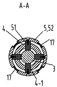
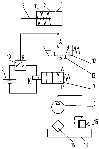
[0018] Such as Figure 1 to Figure 4 As shown, a hydraulic tensioning device includes a cylinder body 1, a piston 2, a piston rod 3, an expansion block mounting seat 4, an expansion block mechanism 5, a mandrel 6, a solenoid valve 7, a power supply 8, a hydraulic pump 9, Pressure relay 10, spring 11, manual reversing valve 12, oil tank 13 and tension spring 17; pressure relay 10 is the pressure relay of model MJCS-02-P-L produced by Wuxi Fulide Hydraulic Machinery Co., Ltd. The right end of the cylinder body 1 has an opening, the left end of the cylinder body 1 has a flange 1-1, the flange 1-1 is provided with a positioning hole 1-1-1 and the left end of the flange 1-1 is provided with a boss 1 -1-2. Flange 1-1 is used to connect with the lathe flange, the boss 1-1-2 is used to closely match with the positioning hole of the lathe flange, and the...


PUM


Abstract

The invention discloses a hydraulic expansion device. The hydraulic expansion device comprises a cylinder body, a piston, a piston rod, an expansion block installing seat, expansion block mechanisms,a mandrel, an electromagnetic valve, a power supply, a hydraulic pump, a pressure relay, springs, a manual reversing valve and an oil box; the piston is slidably connected to the inner cavity of the cylinder body; the piston rod is fixedly connected with the piston, and cone parts are axially arranged on the piston rod; sliding grooves are formed in the expansion block installing seat; expansion blocks are fixedly connected with radial-direction sliding blocks, the radial-direction sliding blocks are slidably connected to the sliding grooves in the expansion block installing seat, and cone faces are arranged on the radial-direction sliding blocks; the mandrel is rotatably connected with the expansion block installing seat, an oil outlet port of the hydraulic pump communicates with an oil inlet port P of the electromagnetic valve, an execution port A of the electromagnetic valve communicates with an oil inlet port P of the manual reversing valve, and an execution port A of the manual reversing valve communicates with a non-rod cavity of the cylinder body; and the power supply, the pressure relay and a terminal of the electromagnetic valve are electrically connected in sequence and form a circuit. The hydraulic expansion device cannot make parts be scrapped because of big expansion force, and cannot make the parts be loosened because of small expansion force when the parts are machined.

Description

technical field [0001] The invention relates to a hydraulic tensioning device. Background technique [0002] When processing typical thin-walled cylindrical parts, when the coaxiality between the outer circle and the inner hole is high according to the design requirements, in order to ensure the machining accuracy, a hydraulic expansion device is usually used, but the hydraulic expansion device in the prior art, its The adjustment of the expansion force depends entirely on the operator's own experience and feeling. When processing typical thin-walled cylindrical parts, if the expansion force is too large, the clamping deformation of the thin-walled cylindrical parts will be too large and the parts will be scrapped. , if the expansion force is too small, the thin-walled cylindrical parts will loosen during processing due to insufficient expansion force. Contents of the invention [0003] The object of the present invention is to provide a hydraulic tensioning device which ...

Claims


Application Information

Patent Timeline
Patent Type & Authority Applications(China)
IPC IPC(8): B23Q3/08B23B31/40
CPCB23B31/40B23B31/4053B23B31/406B23Q3/08B23Q3/082
Inventor 刘剑
Owner 刘剑
Learn More