Automatic supporting and winding type sunshade of front windshield
A front windshield and sunshade technology, applied in the field of sunshade retraction and automatic support, can solve the problems of troublesome disassembly and assembly of roller blinds, low automation level, laborious and laborious, etc., and achieve the effect of compact structure, easy control and reliable movement
- Summary
- Abstract
- Description
- Claims
- Application Information
AI Technical Summary
Problems solved by technology
Method used
Image
Examples
Embodiment 1
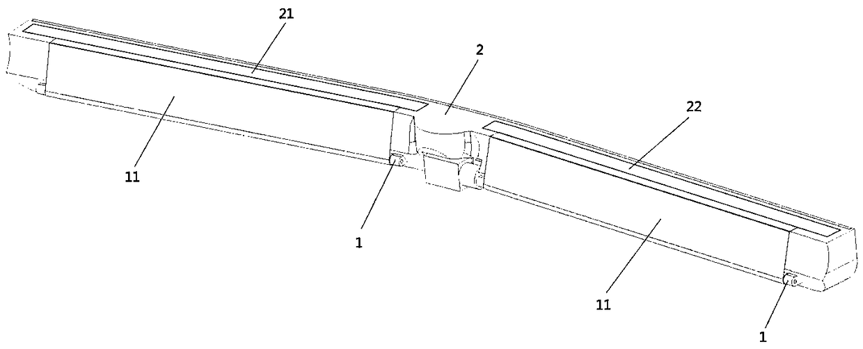
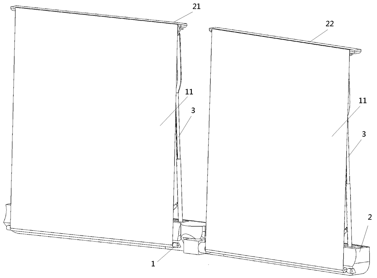
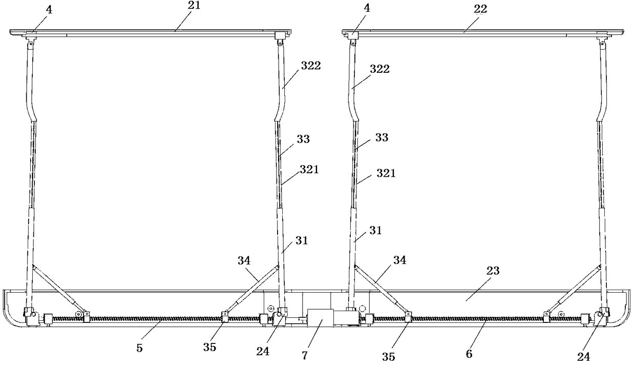
[0024]Embodiment 1, an automatic stretching and retracting sunshade for a front windshield, which is built-in and installed at the bottom of the front windshield. It includes a base 2 fixed on the vehicle body at the bottom of the windshield by screws or bonding. The base 2 has a bow-shaped shell 23 that matches the front windshield, and two sets of retractable roller blinds are installed on the rear of the bow-shaped shell 23 toward the interior of the car. . The reels 1 frame of two groups of retractable roller blinds are symmetrically arranged on the left and right sides of the arcuate housing 23 . The bow-shaped housing 23 top has a limit groove, and the limit in the groove has left and right lifting braces 21,22. The cord 11 free ends of the left and right telescopic roller blinds are fixed on the left and right lifting braces 21,22. The left and right lifting braces 21, 22 are connected with the lifting mechanism.
[0025] The elevating mechanisms of the left and righ...
Embodiment 2
[0028] Embodiment 2. The difference between this embodiment and Embodiment 1 is that the telescopic pendulum adopts a commercially available automatic telescopic rod, and the automatic telescopic rod is connected to the slider through a curved plate. Remove the two-way lead screw, screw nut slider, support rod, universal gear, screw rod, and telescopic rod structure in the first embodiment. The swing driving mechanism of the telescopic swing rod adopts an air cylinder. Each swing link is connected to a cylinder. The overall height of this structure is slightly higher.
Embodiment 3
[0029] Embodiment 3. The difference between this embodiment and Embodiment 1 is that the bevel gear set in Embodiment 1 is removed, and the left two-way lead screw and the right two-way lead screw are each connected to a stepping motor.
PUM
 Abstract
Description
Claims
Application Information
 - R&D
- Intellectual Property
- Life Sciences
- Materials
- Tech Scout
- Unparalleled Data Quality
- Higher Quality Content
- 60% Fewer Hallucinations
Browse by: Latest US Patents, China's latest patents, Technical Efficacy Thesaurus, Application Domain, Technology Topic, Popular Technical Reports.
© 2025 PatSnap. All rights reserved.Legal|Privacy policy|Modern Slavery Act Transparency Statement|Sitemap|About US| Contact US: help@patsnap.com


