
Single-key cap continuous discharging device for keyboard assembling

A discharge device and single-key technology, applied in mixers with rotating stirring devices, packaging, transportation and packaging, etc., can solve the problems of a large number of manpower, low efficiency, high labor costs, etc., achieve low power consumption and reduce labor The effect of strength and concise structure

Active Publication Date: 2019-03-01
深圳市鑫永成科技有限公司
View PDF8 Cites 1 Cited by
  • Summary
  • Abstract
  • Description
  • Claims
  • Application Information

AI Technical Summary

Problems solved by technology

[0002] With the continuous advancement of science and technology, various electronic products have become an indispensable part of people's lives, such as computers, mobile phones, etc., and these electronic products need to be used by a device that can communicate with humans. Such as the keyboard of a personal computer, people need to use it to input instructions and complete data storage and processing operations. With the gradual increase of computer users, the requirements for the quantity and quality of keyboards are getting higher and higher. In the traditional keyboard assembly process, manual There are many steps in the operation, and a lot of manpower is required to assemble the keyboard. During the keyboard assembly process, the keycaps need to be taken out of the keycap storage box one by one, and then pressed on the keyboard shell, which is not only inefficient, but also high in labor costs.

Method used


Image

  • Single-key cap continuous discharging device for keyboard assembling
  • Single-key cap continuous discharging device for keyboard assembling
  • Single-key cap continuous discharging device for keyboard assembling

Examples


Embodiment Construction

[0022] The following will clearly and completely describe the technical solutions in the embodiments of the present invention with reference to the accompanying drawings in the embodiments of the present invention. Obviously, the described embodiments are only some, not all, embodiments of the present invention. Based on the embodiments of the present invention, all other embodiments obtained by persons of ordinary skill in the art without making creative efforts belong to the protection scope of the present invention.

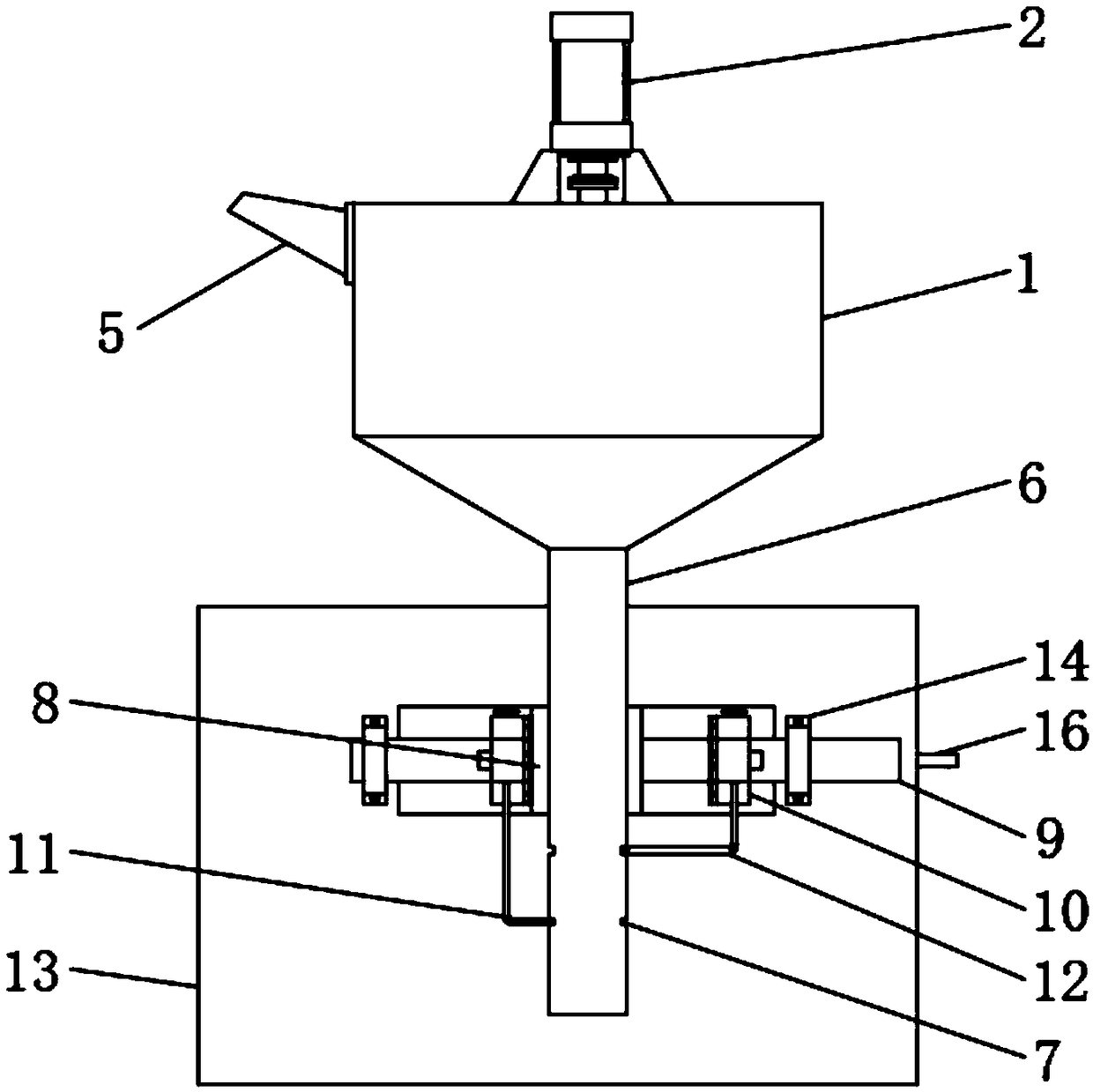
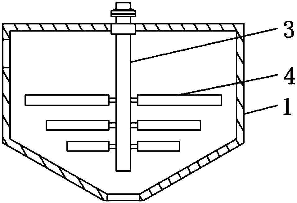
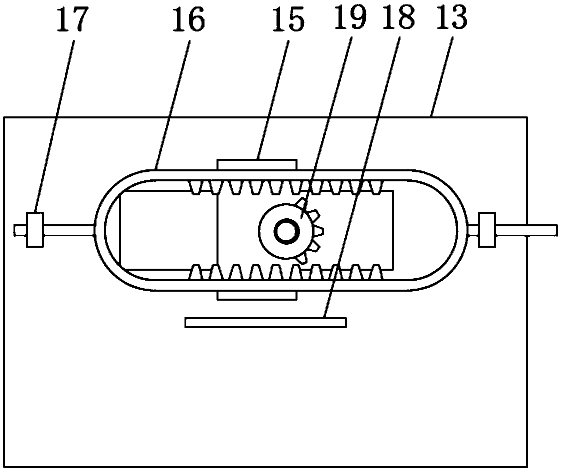
[0023] see Figure 1 to Figure 6 , the present invention provides a technical solution: a single keycap continuous discharging device for keyboard assembly, including a bin 1 for storing keycaps, a cleaning and stirring component and a discharging component. The silo 1 is an inverted conical cylindrical container, and the silo 1 is provided with a cleaning and stirring assembly. The cleaning and agitating assembly includes a cleaning motor 2 for driving the ro...


PUM


Abstract

The invention discloses a single-key cap continuous discharging device for keyboard assembling. The single-key cap continuous discharging device comprises a feed bin for storing keycaps, a cleaning mixing assembly and a discharging assembly, the feed bin is a cylindrical container in the shape of an inverted cone, and the feed bin is provided with the cleaning mixing assembly; the discharging assembly comprises a material guiding pipe and a support plate for bearing the discharging assembly, hollow holes are formed in the pipe wall of the material guiding pipe, and a clamping seat is fixedly connected to the outer pipe wall of the material guiding pipe; and a movable rod penetrating through the left and right sides of the clamping seat is arranged on the clamping seat, two fixed blocks arefixedly connected to the two ends of the movable rod correspondingly, wherein one fixed block positioned on the left side is fixedly connected with a first limiting plate, and one fixed block positioned on the right side is fixedly connected to a second limiting plate. According to the single-key cap continuous discharging device for the keyboard assembling, the structure is concise, an occupiedarea is small, cleaning of the keycaps is realized through the cleaning mixing assembly, single-key cap continuous discharging is realized through the discharging assembly, the discharging is stable,the operation is automatic, the labor intensity of workers is effectively reduced, and human resources are saved.

Description

technical field [0001] The invention relates to the technical field of keyboard assembly, in particular to a single keycap continuous discharging device for keyboard assembly. Background technique [0002] With the continuous advancement of science and technology, various electronic products have become an indispensable part of people's lives, such as computers, mobile phones, etc., and these electronic products need to be used by a device that can communicate with humans and computers. Such as the keyboard of a personal computer, people need to use it to input instructions and complete operations such as data storage and processing. With the gradual increase of computer users, the requirements for the quantity and quality of keyboards are getting higher and higher. In the traditional keyboard assembly process, manual There are many steps in the operation, and a lot of manpower is required to assemble the keyboard. During the keyboard assembly process, the keycaps need to be...

Claims


Application Information

Patent Timeline
Patent Type & Authority Applications(China)
IPC IPC(8): B65D90/64B65D88/68B01F7/20B01F27/906
CPCB65D88/68B65D90/64B01F27/906
Inventor 王卓瑜苏越青何煜旭
Owner 深圳市鑫永成科技有限公司
Learn More