Eureka AIR delivers breakthrough ideas for toughest innovation challenges, trusted by R&D personnel around the world.

Textile machines that produce take-up packages

A textile machine and bobbin technology, applied in the field of textile machines, can solve problems such as station or textile machine shutdown, plastic deformation, control valve failure, etc., and achieve the effect of saving costs

Inactive Publication Date: 2019-03-01
SAURER TECH GMBH & CO KG
View PDF5 Cites 0 Cited by
  • Summary
  • Abstract
  • Description
  • Claims
  • Application Information

AI Technical Summary

Problems solved by technology

[0009] Furthermore, in operating conditions, the entire operating pressure always acts on the diaphragm from behind, which in the long-term entails the risk of plastic deformation in the case of a flexible and fragile component, which in turn may be the cause of premature failure of the control valve and thus lead to Stoppage of workstations or textile machines

Method used


Image

  • Textile machines that produce take-up packages
  • Textile machines that produce take-up packages
  • Textile machines that produce take-up packages

Examples


Embodiment Construction

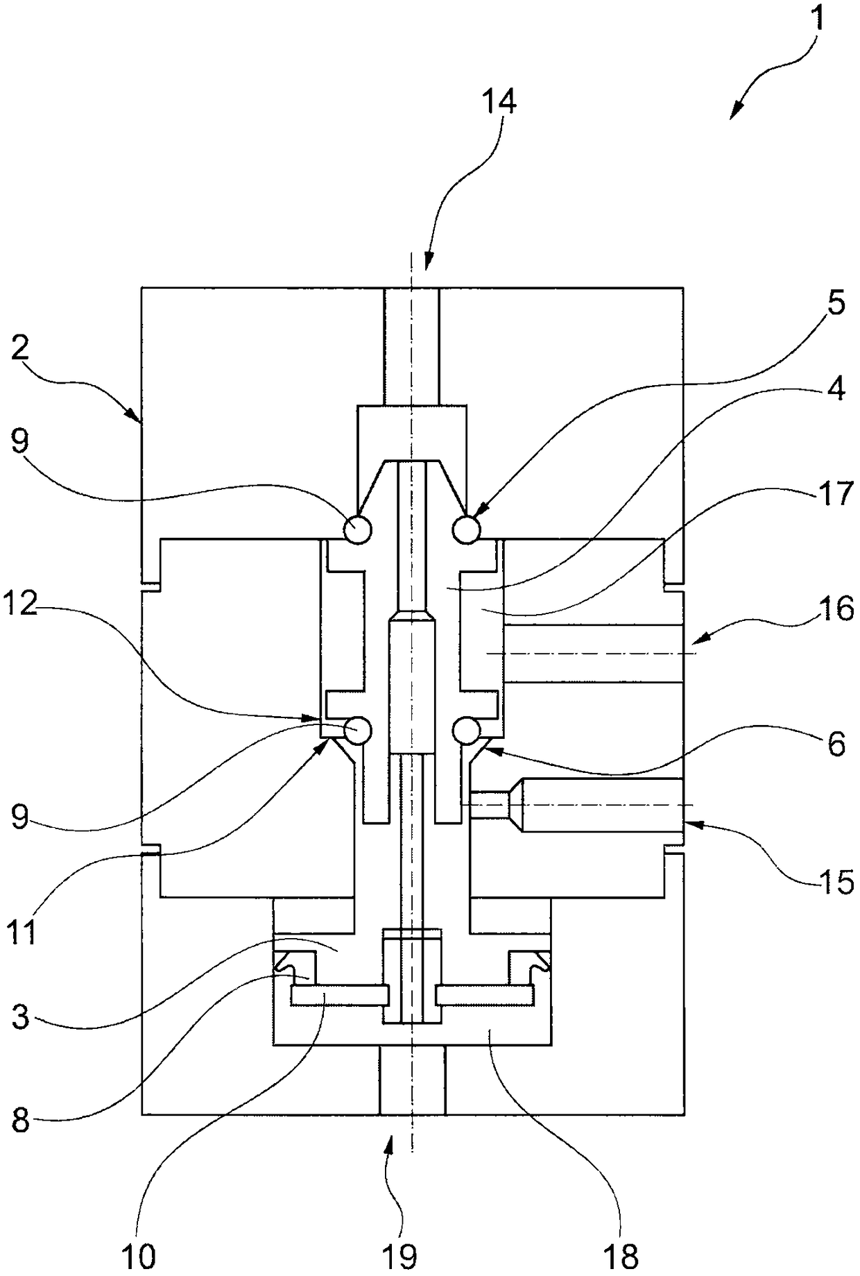
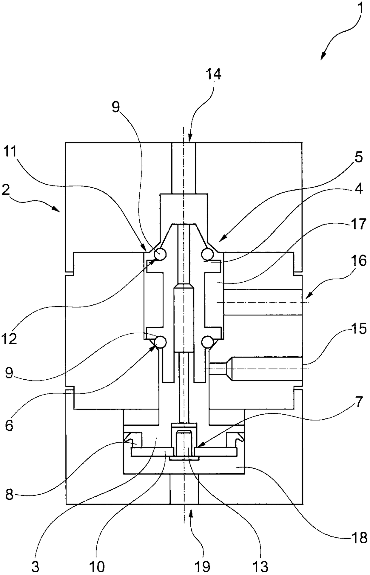
[0061] exist figure 1 The structure of the control valve 1 is shown in a schematic diagram as an example, and the front sealing seat 5 is closed at this time.

[0062] The control valve 1 includes a valve body 2 , a piston 3 and a push rod 4 . Below the piston 3 , a piston seal 8 separates the two air circuits or the front chamber 17 and the rear chamber 18 .

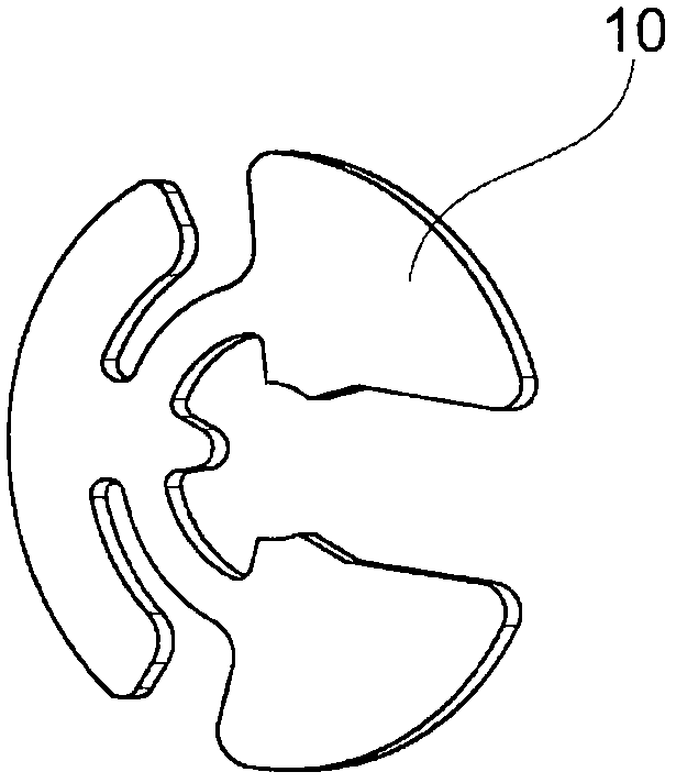
[0063] A support 10 is again arranged below the piston seal 8 . Via the support 10 , not only the piston 3 is fastened to the plunger 4 , but also the piston seal 8 is fastened to the piston 3 .

[0064] In addition, in this embodiment, the valve body 2 is divided into three sections and provided with a plurality of contact surfaces 11 against which respective corresponding surfaces 12 can be abutted, said corresponding surfaces being formed on the front sealing seat 5 and the front sealing seat 5 of the push rod 4 . On the rear sealing seat 6.

[0065] Via the main channel 14 , air flows through a continuous small ...


PUM


Abstract

The invention relates to a textile machine that produces take-up packages with control valves (1), whereby the control valves (1) each have a valve body (2), a piston (3) and a plunger (4), whereby the plunger (4) comprises a front seal seat (5) and a rear seal seat (6) as well as seals (9), with which outlets, such as a main line (14), a pilot line (19), a connection (16) and at least one vent (15) are alternately sealable in the valve body (2), and the piston (3) has a piston seal (8) that separates two air circuits from each other. Contact surfaces (11) are designed in the valve body, at which the corresponding surfaces (12) of the front and rear seal seats 5, 6 of the plunger 4 can be brought into abutment.

Description

technical field [0001] The invention relates to a textile machine for manufacturing winding bobbins with a control valve. Background technique [0002] On textile machines for producing wound bobbins, such as twisters and direct twisters, it is common to use sensor devices which monitor various operating and process states. For example, barometric sensor arrangements, barometric electrical sensor arrangements or electromagnetic sensor arrangements are known here. Devices such as actuating bobbin lifting, yarn clamping, yarn cutting or spindle stopping are controlled with signals from sensor devices. [0003] It is also known that so-called pilot valves can be arranged between the sensor device and the device to be controlled, which are also mechanically designed in the form of pressure-touch valves or pneumatically actuated valves, for example. [0004] During the twisting process, the presence of the yarn is monitored, for example, by means of a mechanical element that re...

Claims


Application Information

Patent Timeline
Patent Type & Authority Applications(China)
IPC IPC(8): D01H13/16
CPCD01H13/1683B65H54/707B65H63/036F16K11/044B65H2701/31F16K31/1223D01H13/00D01H9/08B65H54/70D01H13/16
Inventor M·戴伦乔治·海嫩谢尔盖·辛戈
Owner SAURER TECH GMBH & CO KG
Why Eureka
Eureka Blog
Learn More