Side mold mechanism for concrete mold spraying

A technology of concrete and side formwork, which is applied in earth-moving drilling, wellbore lining, tunnel lining and other directions, can solve the problems of prolonging the construction period, aggravating concrete leakage and waste, etc., and achieves the effect of improving construction quality, improving construction efficiency and reducing consumption.

Pending Publication Date: 2019-03-01
SICHUAN LANHAI ENG EQUIP MFG CO LTD
View PDF12 Cites 2 Cited by
  • Summary
  • Abstract
  • Description
  • Claims
  • Application Information

AI Technical Summary

Problems solved by technology

[0003] In order to ensure that the concrete support layer can meet the strength requirements within a certain period of time, it is necessary to add a large amount of concrete quick-setting agent to the concrete, and the sprayed concrete has a high rebound rate, which causes unnecessary waste. After the support is formed, its surface If the degree of cleanliness is poor, the surface needs to be reshaped, which prolongs the construction period
[0004] During the practice of spraying or pouring the initial support of the tunnel, the applicant found that the rebound rate of the concrete and the use of concrete quick-setting agents can be effectively reduced by using the formwork mechanism. There will inevitably be unevenness in the excavation surface, and there will be gaps to varying degrees between the supporting surface of the erected steel arch and the excavation surface, and there will also be gaps between the contact surface of the formwork and the steel arch, making During the mold spraying process using the formwork mechanism, the injected concrete will leak from the gap, and at the same time, when the concrete is injected into the mold cavity of the supporting mold, due to the gravity of the concrete itself and the impact force of the concrete spraying, it will cause or even aggravate the concrete from the support. The problem of leakage in the mold cavity

Method used


Image

  • Side mold mechanism for concrete mold spraying
  • Side mold mechanism for concrete mold spraying
  • Side mold mechanism for concrete mold spraying

Examples


Embodiment 1

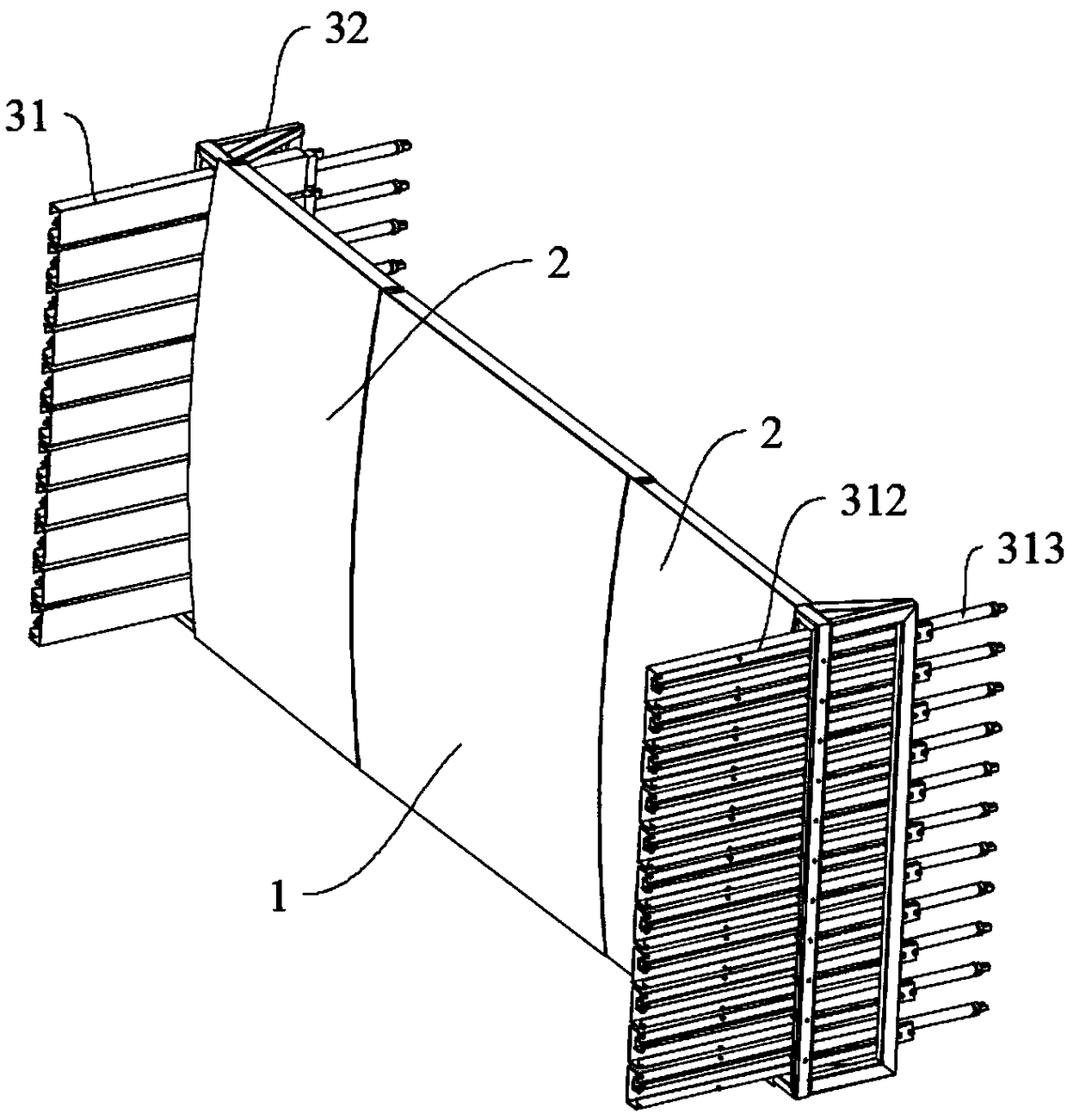
[0032] As shown in the figure, the sideform mechanism 3 for concrete mold spraying includes a sideform support 32 and a telescopic side formwork assembly, the sideform support 32 is fixed on the edge of the formwork, and the sideform assembly is installed on the sideform support 32, and It can expand and contract in the direction perpendicular to the formwork, and the protruding side formwork components can be against the rock surface of the tunnel, so that the rock surface, formwork and side formwork components can cooperate with each other to form a mold cavity.

[0033] The side formwork assembly is composed of several side formwork units 31 arranged continuously, and each side formwork unit 31 can perform independent telescopic movement. The side template unit 31 includes an inner stroke frame 311, a side mold cover 312 and a telescopic mechanism, and the side mold cover 312 is slidably sleeved on the inner stroke frame 311; the telescopic mechanism is configured as an oil ...

Embodiment 2

[0043] An example of applying the side form mechanism 3 in Embodiment 1 to a combined formwork mechanism is disclosed.

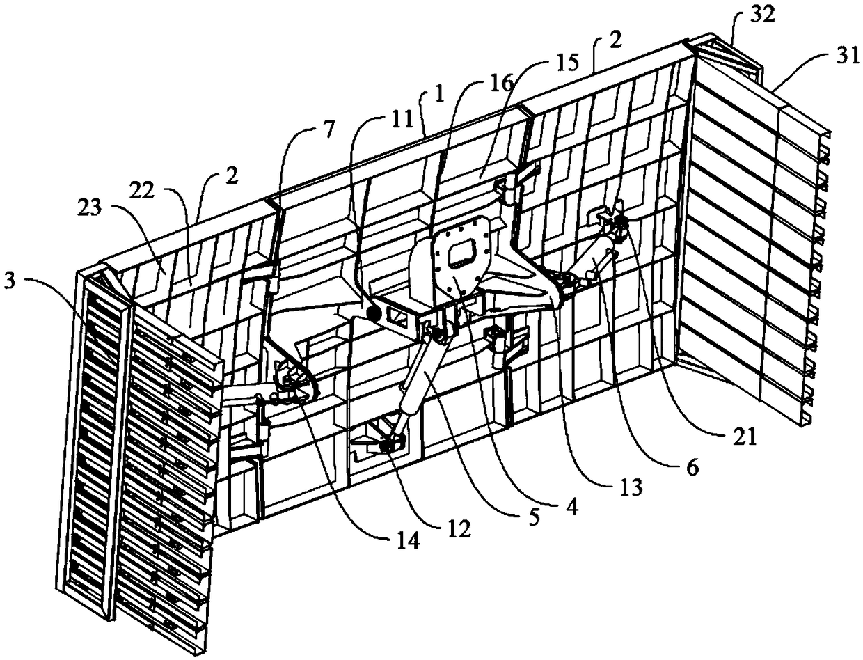
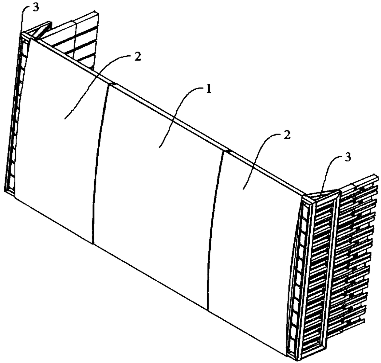
[0044] A combined formwork mechanism for concrete mold spraying, the formwork mechanism includes a main formwork 1, an auxiliary formwork 2, a side formwork mechanism 3, a formwork support 4, a pitch cylinder 5, a side cylinder 6 and a hinge seat 7. One or both sides of the main formwork 1 are foldably connected with the auxiliary formwork 2, and the formwork mechanism can cover more than two adjacent steel arches erected on the tunnel driving surface as a whole at any height; the main formwork 1 and the auxiliary formwork 2 The two sides are connected through the hinge seat 7; the piston rod sub-formwork 2 of the lateral oil cylinder 6 is connected through the hinge support 21, and the backs of both sides of the main formwork 1 are respectively provided with side cylinder hinge seat plates 13 protruding vertically from the main formwork 1. The cylinder body...

Embodiment 3

[0055] In this embodiment, on the basis of Embodiment 2, when the formwork assembly and the sideform mechanism 3 are in use, the steel arch frame must be built independently of the tunnel, that is, when the steel arch frame is not erected, the sideform mechanism 3. The template mechanism and the rock surface directly form a mold cavity for direct injection pouring.


PUM


Abstract

The invention discloses a side mold mechanism for concrete mold spraying. The side mold mechanism for concrete mold spraying comprises a side mold supporting frame and a telescopic side mold plate assembly, wherein the side mold supporting frame is fixed to the edge part of a mold plate; the side mold plate assembly is mounted on the side mold supporting frame, and can extend and retract in the direction perpendicular to the mold plate, and the extended side mold plate assembly can abut against the rock surface of a tunnel, and thus the rock surface, the mold plate and the side mold plate assembly can match with each other to form a mold cavity. Through the side mold mechanism for concrete mold spraying matching with a tunnel primary supporting mold plate mechanism, the mold cavity is formed among a side mold plate mechanism, a mold plate mechanism and the rock surface, and thus a mold spraying operation can be carried out directly when a steel arch is not constructed; the phenomenon of material leaking caused by a gap between the mold plate mechanism and the steel arch or between the steel arch and the rock surface is avoided even if the pouring construction is performed on the mold cavity formed by being matched with the steel arch, and thus the dosage of pouring raw materials is further saved, and the construction quality of primary supporting spray pouring is improved.

Description

technical field [0001] The invention belongs to the technical field of engineering construction, and in particular relates to a side form mechanism for concrete form spraying. Background technique [0002] Among the existing tunnel engineering machinery, the concrete sprayer is a relatively common construction machinery. The working principle of the concrete spraying machine is to use compressed air to transport the pre-mixed concrete mixture to the nozzle of the spraying machine through the pipeline, and form a bundle after being mixed with accelerator. On the sprayed surface, the quick-setting agent makes the concrete set and harden quickly, thus forming a concrete support layer. Shotcrete technology has been widely used in various engineering fields due to its simple process. [0003] In order to ensure that the concrete support layer can meet the strength requirements within a certain period of time, it is necessary to add a large amount of concrete quick-setting agent...

Claims


Application Information

Patent Timeline
Patent Type & Authority Applications(China)
IPC IPC(8): E21D11/10
CPCE21D11/102
Inventor 蓝传雯
Owner SICHUAN LANHAI ENG EQUIP MFG CO LTD
Why Eureka
Try Eureka