Dynamic plugging device during shaft kiln distribution

A plugging device and shaft kiln technology, which is applied in the direction of furnaces, vertical furnaces, lighting and heating equipment, etc., can solve high-demand problems, achieve the effects of simple and compact structure, reduce the risk of air leakage, and improve use efficiency

Pending Publication Date: 2019-03-01
ACRE COKING & REFRACTORY ENG CONSULTING CORP DALIAN MCC
View PDF0 Cites 0 Cited by
  • Summary
  • Abstract
  • Description
  • Claims
  • Application Information

AI Technical Summary

Problems solved by technology

However, the ambient temperature in the shaft kiln is relatively high, there is a lot of dust, and the plugging plate is also subjected to a large amount of impact of limestone when the material is unloaded. Therefore, setting up a dynamic device at this position has high requirements for itself

Method used


Image

  • Dynamic plugging device during shaft kiln distribution
  • Dynamic plugging device during shaft kiln distribution
  • Dynamic plugging device during shaft kiln distribution

Examples


Embodiment Construction

[0023] The specific embodiment of the present invention will be further described below in conjunction with accompanying drawing:

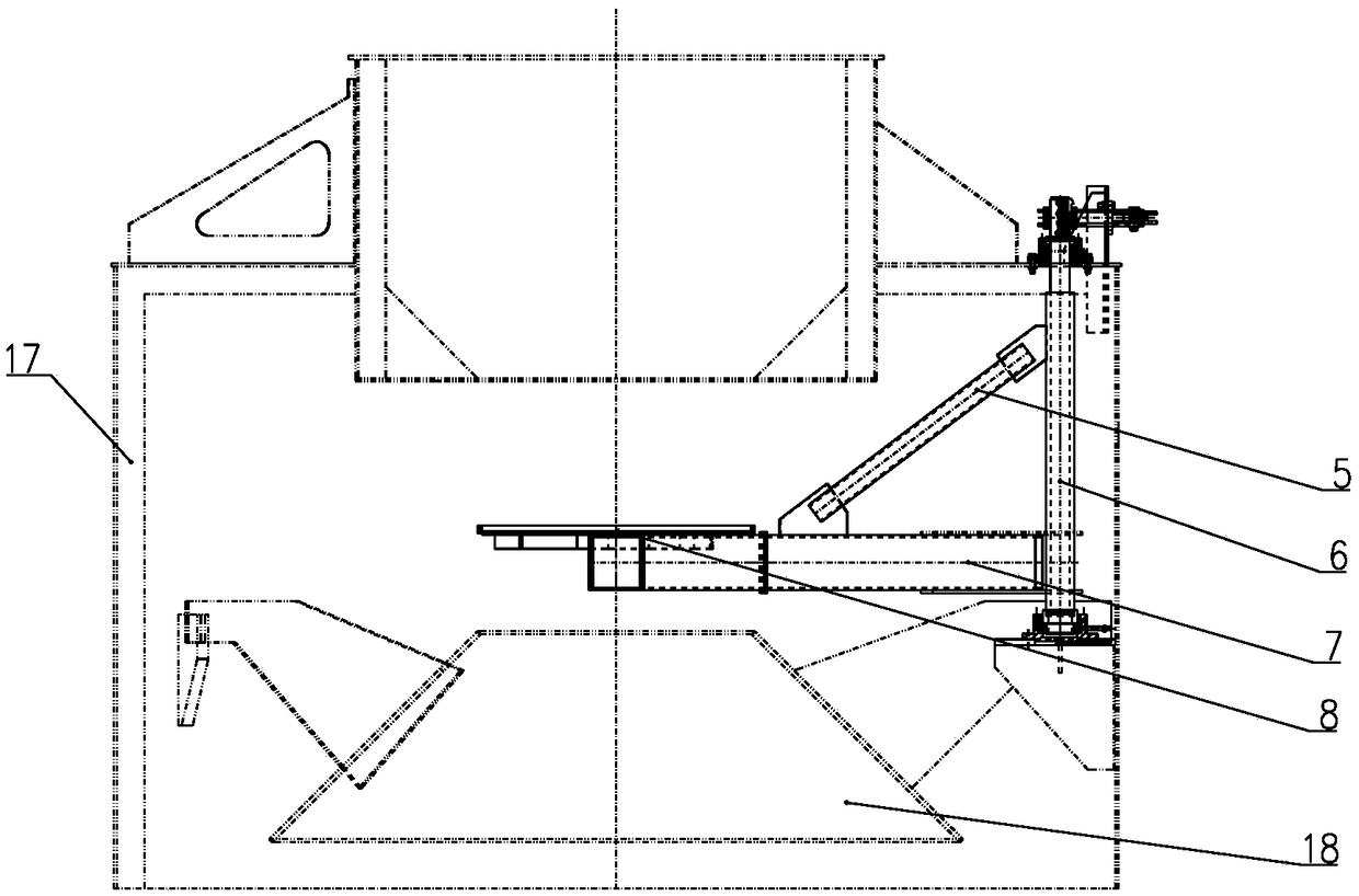
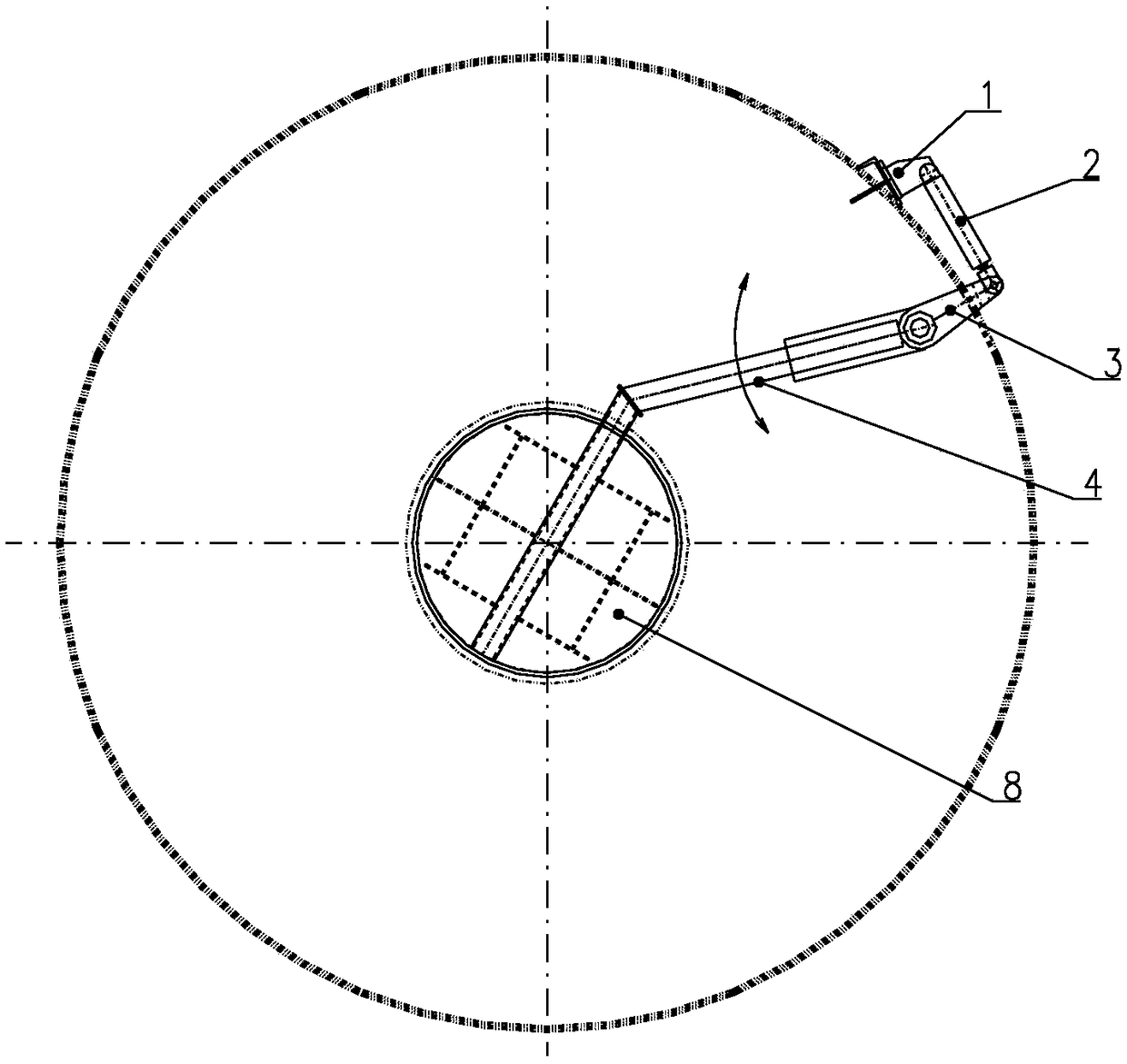
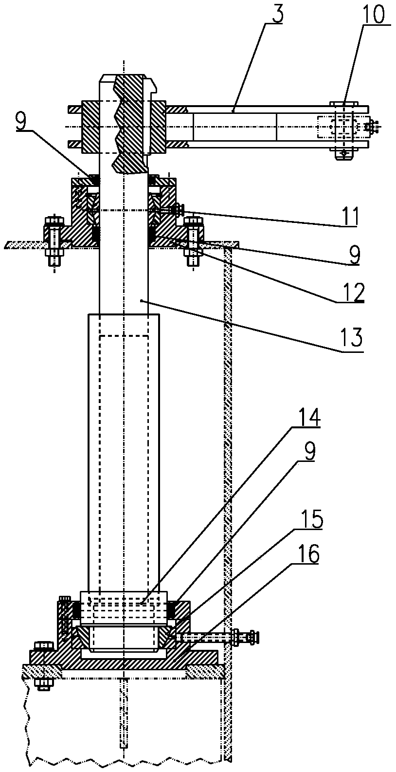
[0024] Such as figure 1 , figure 2 As shown, a dynamic plugging device for vertical kiln material distribution according to the present invention is installed above the conical distributor 18 at the feed inlet of the vertical kiln. Conical cylindrical structure; the dynamic blocking device includes an actuator support 1, a linear actuator 2, a short swing arm 3, a vertical shaft, a bracket 4 and a sealing disc 8; the actuator support 1 is arranged on a vertical On the outer wall of the kiln 17, the tail end of the linear actuator 2 is hinged on the actuator support 1, and the power output end of the linear actuator 2 is hinged to one end of the short swing arm 3 through a pin 10; the short swing arm 3 extends into the kiln body It is connected with one end of the bracket 4, and can drive the bracket 4 to rotate around the vertical axis under th...


PUM


Abstract

The invention relates to a dynamic plugging device during shaft kiln distribution. The dynamic plugging device is installed above a conical distributor at a feeding inlet of a shaft kiln and comprisesan executor support, a linear executor, a short swing arm, a vertical shaft, a bracket and a plugging disc; the executor support is arranged on the outer wall of the shaft kiln; the tail end of the linear executor is hinged to the executor support; the power output end of the linear executor is hinged to one end of the short swing arm through a pin shaft; the short swing arm extends into a kiln body, is connected with one end of the bracket, and can drive the bracket to rotate around the vertical shaft under the function of the linear executor; the plugging disc is fixed to the bracket and horizontally swings along with the bracket; and one end point of the swinging path of the plugging disc is located over the conical distributor and can completely shield an upper opening of the distributor, and the other end point is located on the outer side of the upper opening of the distributor. The dynamic plugging device during shaft kiln distribution is used for being matched with the conicaldistributor to achieve various distribution of material faces inside the kiln, and is simple in structure, convenient to operate, low in failure rate and convenient to maintain.

Description

technical field [0001] The invention relates to a material distribution device for a shaft kiln, in particular to a dynamic blocking device for material distribution of a shaft kiln. Background technique [0002] Lime shaft kiln is an important thermal kiln in the lime industry. The material layer and surface distribution of the lime shaft kiln play a key role in the reaction of materials in the lime shaft kiln. According to different situations, blocking and opening the upper opening of the conical distributor can effectively control the distribution state of the material surface of the vertical kiln material layer. However, the ambient temperature in the shaft kiln is relatively high, there is a lot of dust, and the plugging plate is also subjected to a large amount of impact of limestone when the material is unloaded. Therefore, setting up a dynamic device at this position has high requirements for itself. In order to maintain the long-term stable and continuous product...

Claims


Application Information

Patent Timeline
IPC IPC(8): F27B1/20
CPCF27B1/20
Inventor 徐大鹏白城关世文霍欣
Owner ACRE COKING & REFRACTORY ENG CONSULTING CORP DALIAN MCC
Why Eureka
Try Eureka