Actual-working-condition-based precision retention test device and method of ball screw pair

A ball screw pair and precision maintenance technology, which is used in measuring devices, testing of mechanical components, and testing of machine/structural components, etc., can solve the problems of inability to carry out precision maintenance tests, lack of loading capacity, and lack of test methods. , to achieve the effect of low manufacturing cost, short manufacturing cycle, convenient maintenance and maintenance

Pending Publication Date: 2019-03-01
SHENYANG LIGONG UNIV
View PDF7 Cites 4 Cited by
  • Summary
  • Abstract
  • Description
  • Claims
  • Application Information

AI Technical Summary

Problems solved by technology

[0004] Since foreign countries have always been in a state of technical blockade in the accuracy maintenance test of ball screw pairs, there are still great deficiencies in domestic research on related aspects, and the test devices for the performance research of ball screw pairs are mainly focused on performance. In terms of testing, and most of the test devices still do not have the loading capacity, cannot simulate the actual working conditions during processing, let alone carry out precision maintenance tests, and lack relevant test methods
[0005] Due to the lack of relevant equipment in China that can perform precision maintenance and life tests on ball screw pairs, we are looking for solutions for related domestic industries

Method used


Image

  • Actual-working-condition-based precision retention test device and method of ball screw pair
  • Actual-working-condition-based precision retention test device and method of ball screw pair
  • Actual-working-condition-based precision retention test device and method of ball screw pair

Examples


Embodiment Construction

[0032] The present invention will be further described in detail below in conjunction with the accompanying drawings and specific embodiments.

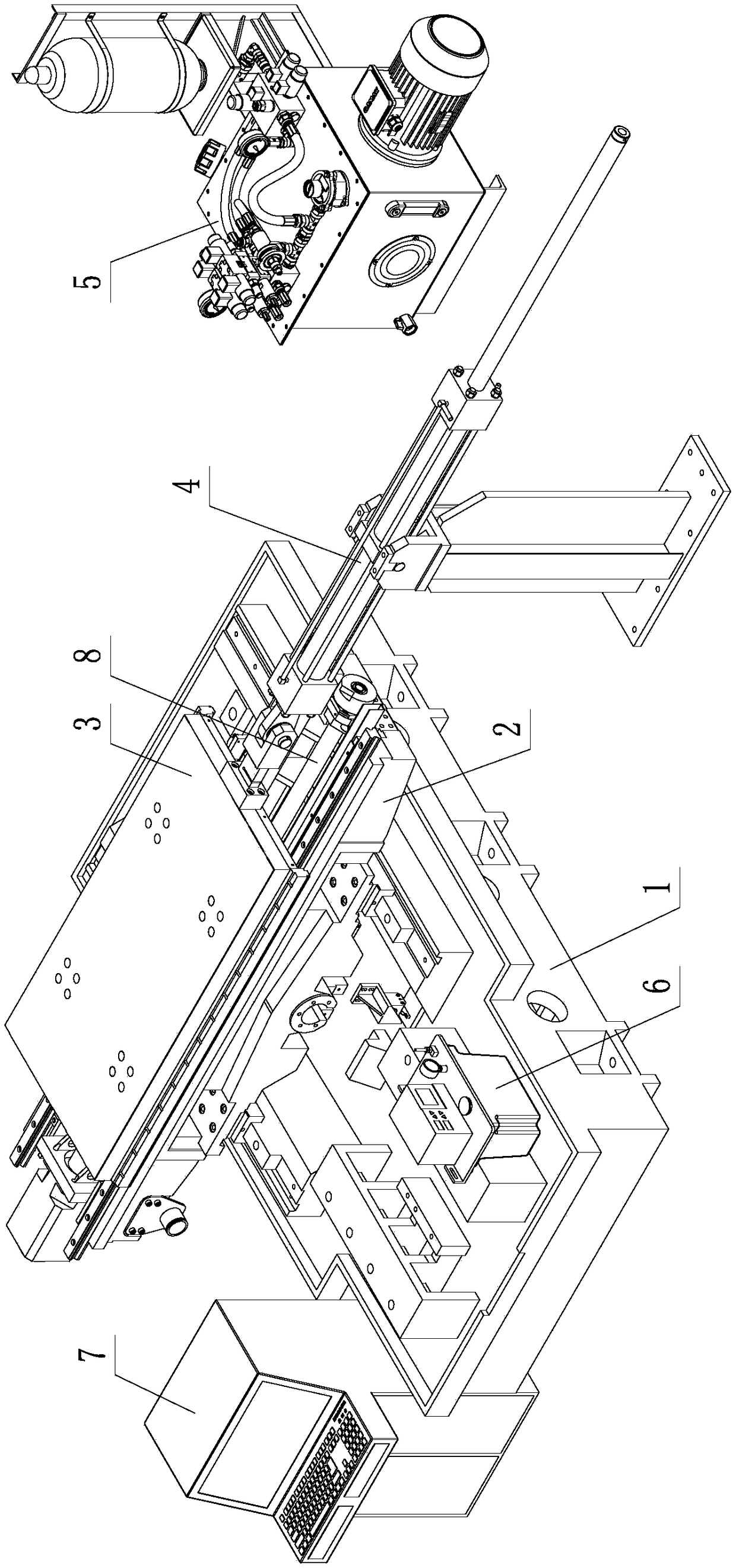
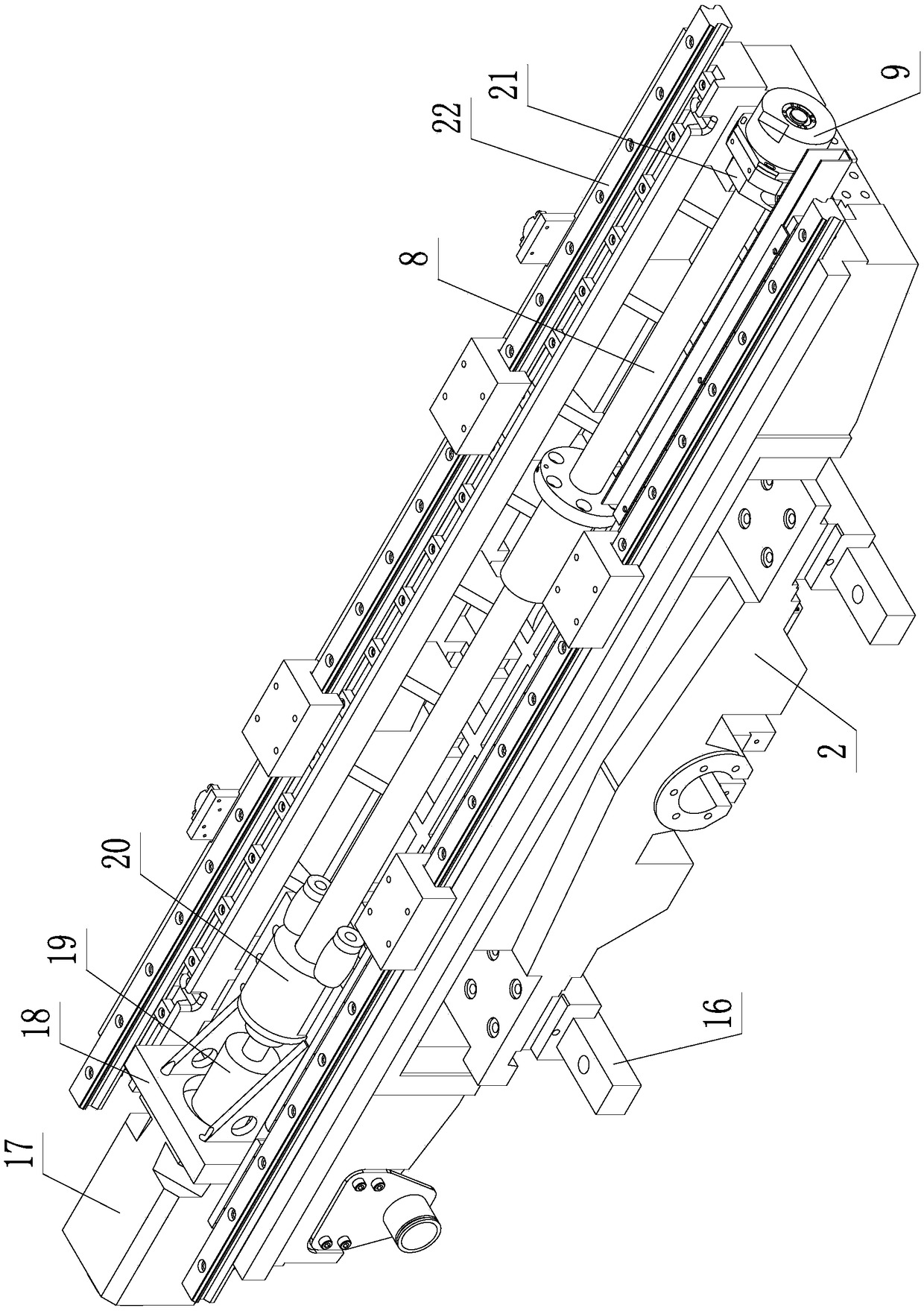
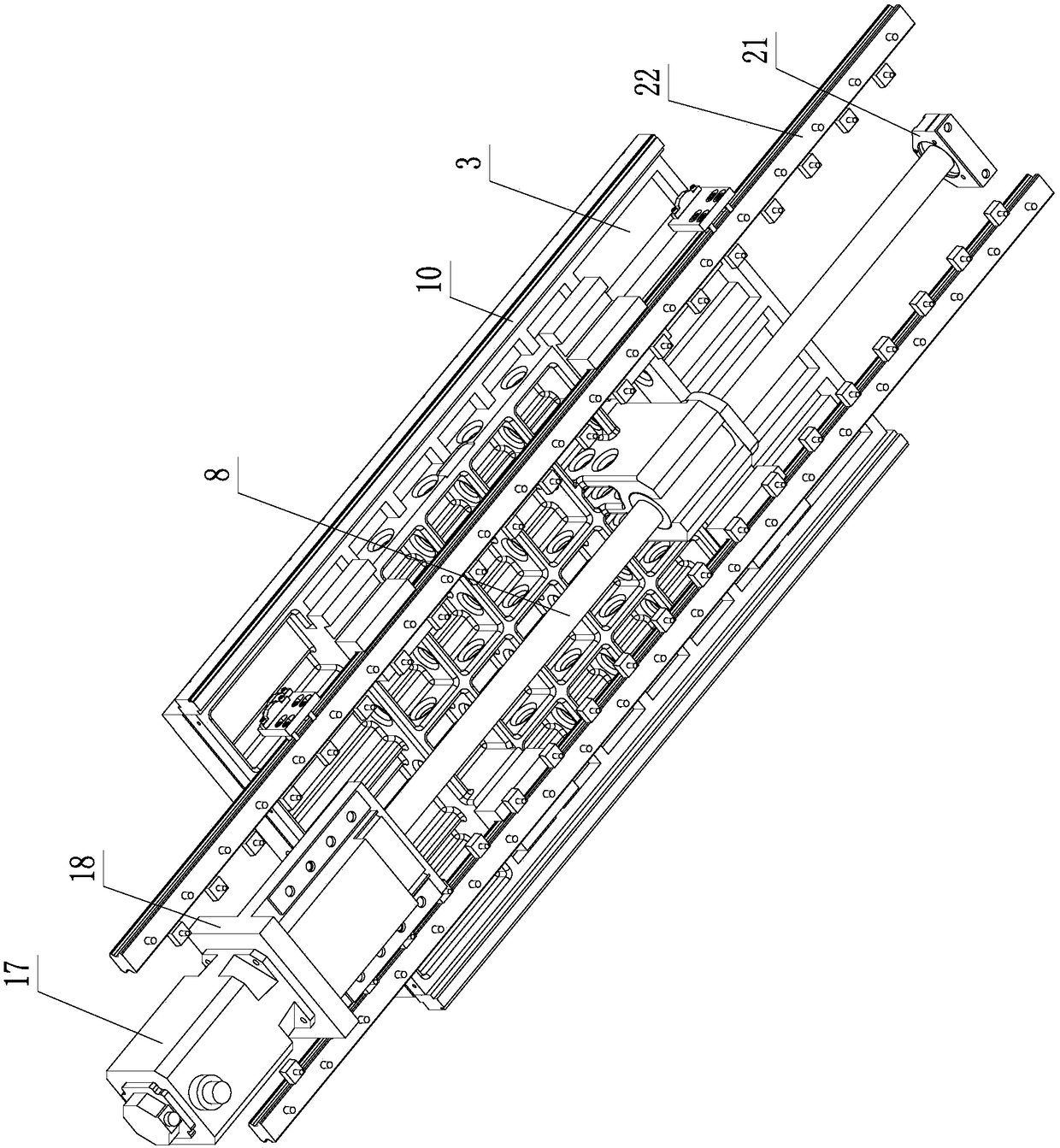
[0033] Such as Figure 1~4 As shown, a ball screw pair accuracy maintenance test device based on real working conditions includes a bed 1, a saddle 2, a workbench 3, a force applying mechanism 4, a hydraulic station 5, a lubrication mechanism 6, a console 7 and The ball screw sub-test piece 8; the sliding saddle 2 is fixedly installed above the bed 1; the worktable 3 is arranged above the sliding saddle 2; the ball screw sub-test piece 8 is connected between the sliding saddle 2 and the worktable 3, the ball screw sub-test piece 8 is provided with lubricating oil by the lubricating mechanism 6; the force applying mechanism 4 is arranged on the ground, the force applying mechanism 4 is connected with the workbench 3, and the hydraulic station 5 is used as the force applying mechanism 4 The power source; the console 7 is used to set th...


PUM


Abstract

The invention provides an actual-working-condition-based precision retention test device and method of a ball screw pair. The device comprises a lathe bed, a sliding saddle, a work table, a force applying mechanism, a hydraulic station, a lubrication mechanism, a console and a ball screw pair test piece. The lathe bed, the sliding saddle, the work table, and the console employ lathe bed parts matching the ball screw pair test piece that is connected between the sliding saddle and the work table. The force applying mechanism is arranged on the ground and is connected with the work table. A circular grating ruler is arranged at the tail of the ball screw pair test piece. A linear grating ruler is arranged on the work table. A proportional valve or a servo valve is arranged in the hydraulic station. In addition, the method includes the following steps that: the running length or running time of the ball screw pair test piece is set by the console; the ball screw pair test piece is operated; after operation ending, the operation precision of the ball screw pair test piece is measured by using the circular grating ruler and the linear grating ruler; the operation and measurement processes are repeated until the operation precision is lost completely; and on the basis of the obtained operation precision data, the precision retention rule of the ball screw pair test piece is studied.

Description

technical field [0001] The invention belongs to the technical field of precision retention testing and research of rolling functional parts, and in particular relates to a test device and method for precision retention of a ball screw pair based on real working conditions. Background technique [0002] As a precision transmission component, the ball screw pair has the advantages of high transmission efficiency, high transmission precision, stable transmission, low wear, long life, no axial clearance, high rigidity, etc. It has been widely used in automation, aviation, automobile and other fields , and the demand is also increasing rapidly, while the performance requirements of the ball screw pair are also increasing. [0003] Taking the field of high-end CNC machine tools as an example, the accuracy retention and service life of the ball screw pair are crucial to the overall performance, machining accuracy, and equipment life of the CNC machine tool. [0004] Since foreign ...

Claims


Application Information

Patent Timeline
Patent Type & Authority Applications(China)
IPC IPC(8): G01M13/027
CPCG01M13/027
Inventor 焦可如舒启林鑫龙张玉璞
Owner SHENYANG LIGONG UNIV
Why Eureka
Try Eureka