
Onboard ultra-wideband radar front-view imaging system

An ultra-wideband radar and forward-looking imaging technology, applied in the field of environmental perception, can solve the problems of not being able to achieve good results, increase the difficulty of obstacle detection and identification, etc., achieve strong penetration performance, strong penetration ability, and improve imaging Effect of Resolution and Accuracy

Pending Publication Date: 2019-03-01
HUNAN NOVASKY ELECTRONICS TECH
View PDF6 Cites 11 Cited by
  • Summary
  • Abstract
  • Description
  • Claims
  • Application Information

AI Technical Summary

Problems solved by technology

However, in the actual off-road environment, the material composition, size, position and attitude of obstacles have no fixed form, and the overgrown vegetation and rough soil on the ground will also form strong and large reflections, which increases the difficulty of obstacle detection and recognition. difficulty
That is, in the process of driving unmanned vehicles, especially in the off-road environment, that is, when the road conditions are relatively complex, there are concave obstacles and leaf clusters, conventional sensors such as stereo vision, infrared cameras and lidars cannot obtain good results. As a result, the detection of concave obstacles in the wild environment and the detection of convex obstacles hidden under the leaf clusters have always been difficult problems for unmanned walking platforms.

Method used


Image

  • Onboard ultra-wideband radar front-view imaging system
  • Onboard ultra-wideband radar front-view imaging system
  • Onboard ultra-wideband radar front-view imaging system

Examples


Embodiment Construction

[0026] The present invention will be further described in detail below in conjunction with the accompanying drawings and specific embodiments.

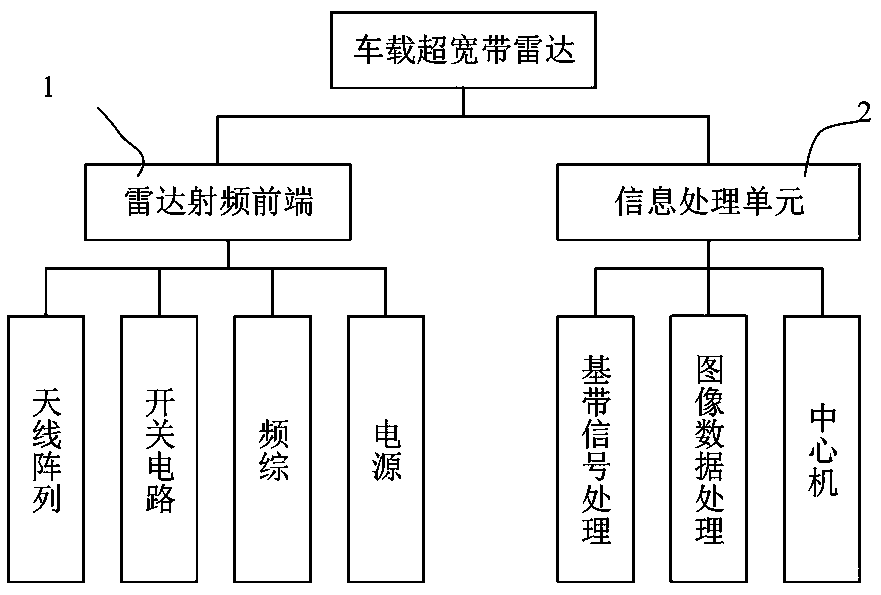
[0027] Such as figure 1 As shown, the vehicle-mounted ultra-wideband radar forward-looking imaging system of the present invention adopts a compact integrated design, including:

[0028] The radar radio frequency front end 1 includes an antenna, a frequency synthesizer and a switch circuit, the antenna is used to complete the transmission and reception of ultra-wideband continuous wave signals, the frequency synthesizer includes a transmitter and a receiver, and the switch circuit is used to complete multi-transmit and multi-receive time-sharing operations;

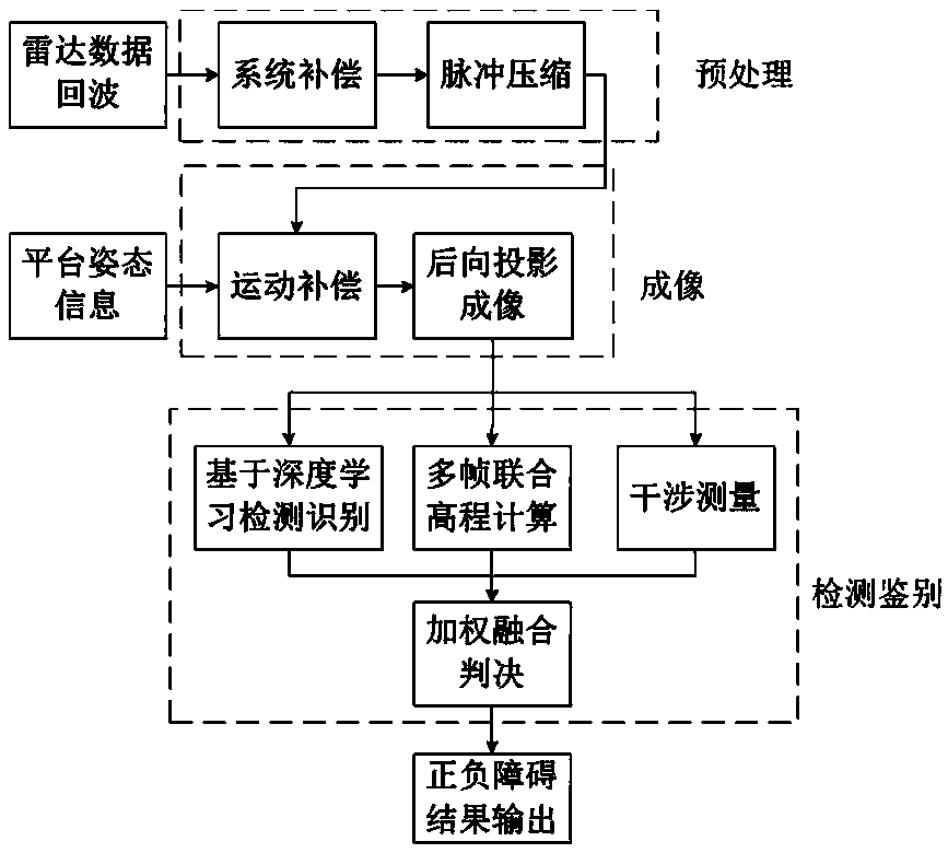
[0029] Information processing unit 2, including a signal processor and a data processor, the signal processor is used to generate system timing control and a large bandwidth step frequency signal and sample the radar step frequency echo signal, and finally realize near-field forw...


PUM


Abstract

An onboard ultra-wideband radar front-view imaging system comprises a radar radiofrequency front end including an antenna, a frequency synthesizer, and a switching circuit, wherein the antenna is usedfor transmitting and receiving an ultra-wideband continuous wave signal, the frequency synthesizer includes a transmitter and a receiver, and the switching circuit is used for achieving the multi-transmitting multi-receiving time-sharing operation; an information processing unit including a signal processor and a data processor, wherein the signal processor is used for generating system timing control and a large-bandwidth step-frequency signal, sampling a radar step-frequency echo signal, and finally performing a near-field front-view imaging process and transmitting a result to the data processor, and the data processor processes the signal and detects the signal by a detection algorithm in the image domain, and finally detects and identifies positive and negative obstacles and obstacles behind hidden objects such as leaf leafages. The onboard ultra-wideband radar front-view imaging system is easy to achieve, good in environmental sensing effect and high in resolution.

Description

technical field [0001] The invention mainly relates to the technical field of environment perception of an unmanned platform, in particular to a vehicle-mounted ultra-wideband radar forward-looking imaging system. Background technique [0002] Obstacle detection is the basic requirement for the environment perception of ground unmanned platforms, and it is also the main application bottleneck that restricts the application of unmanned platforms in various fields. Traditional environmental sensing methods, such as optics, infrared sensors, and lidar, basically acquire the light reflectivity of materials in the scene. Different from photoelectric means, the radar image reflects the dielectric constant discontinuity of the scene ahead, and the material or surface discontinuity between the obstacle and the background appears as a highlight in the image. However, in the actual off-road environment, the material composition, size, position and attitude of obstacles have no fixed ...

Claims


Application Information

Patent Timeline
Patent Type & Authority Applications(China)
IPC IPC(8): G01S13/90G01S13/93
CPCG01S13/90G01S13/931
Inventor 贺玉贵唐良勇王生水韩明华
Owner HUNAN NOVASKY ELECTRONICS TECH
Learn More