Optical sub module and optical module

An optical sub-module and optical device technology, applied in the field of optical communication, can solve the problems of poor optical transmission effect of the optical sub-module, and achieve the effect of improving the influence and solving the effect of affecting the optical path.

Active Publication Date: 2019-03-01
HISENSE BROADBAND MULTIMEDIA TECH
View PDF6 Cites 1 Cited by
  • Summary
  • Abstract
  • Description
  • Claims
  • Application Information

AI Technical Summary

Problems solved by technology

[0005] The present invention provides an optical sub-module and an optical module to solve the problem of poor light transmission effect of existing optical sub-modules

Method used


Image

  • Optical sub module and optical module
  • Optical sub module and optical module
  • Optical sub module and optical module

Examples


Embodiment Construction

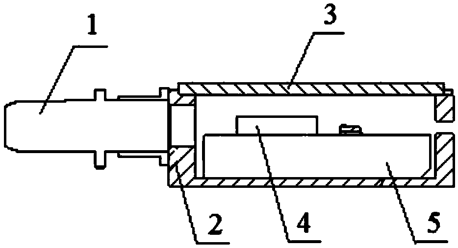
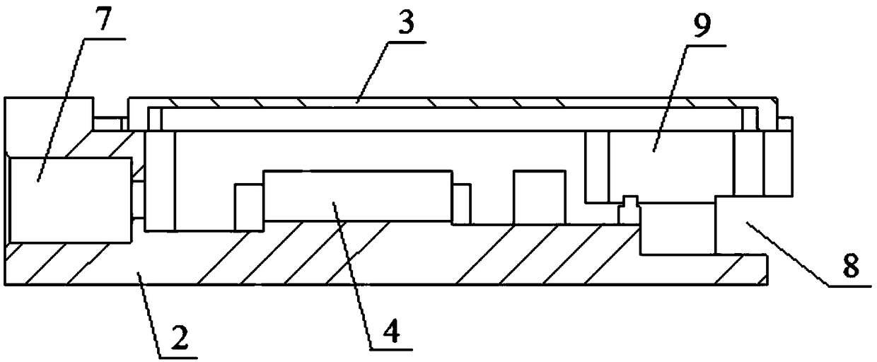
[0023] image 3 Schematic diagram of the structure of the optical sub-module provided by the embodiment of the present invention; Figure 4 A side view of an optical sub-module provided by an embodiment of the present invention.

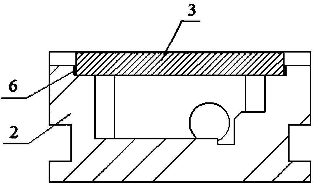
[0024] see image 3 and Figure 4 , the optical sub-module provided by the embodiment of the present invention is used for such as Figure 11 In the optical module shown, the optical sub-module is electrically connected to the circuit board component to form an optical module, the circuit board component is connected to an external host computer to realize power supply and electrical signal transmission, and the optical sub-module is connected to an optical transmission medium such as an external optical fiber to realize optical transmission. transmission. Specifically, the optical sub-module provided in this embodiment includes: a housing 2 , an upper cover 3 and an optical device 4 .

[0025] The casing 2 is a frame-like structure with an open...


PUM


Abstract

The invention discloses an optical sub module and an optical module. The optical module comprises an optical sub module and a circuit board. In the optical sub module, an upper cover is arranged in ahousing to form a receiving cavity; and an optical device is arranged in the receiving cavity and fixed on the bottom surface of the housing. The upper cover plate includes a top plate and side platesperpendicular to the top plate; the side plates are connected with the housing by glue layers, wherein the expansion coefficient of the glue layer is respectively greater than the expansion coefficient of the housing and the expansion coefficient of the upper cover plate. Therefore, when the optical sub module is in a high-temperature baking state, the expansion degree of the glue layer is largerthan those of the housing and the upper cover plate. The expanded glue generates thrusts on the housing and the upper cover plate; and when the thrusts are applied to the side plates, moments are formed. Compared with the prior art, the optical sub module and the optical module have the following beneficial effects: the upper cover plate is easy to deform by being compared with the housing and thus deformation transmission to the housing is prevented; since the deformation amount of the housing is small, the situation affecting the optical path is improved, so that a problem that the affectedoptical path occurs easily at the existing optical sub module and thus the optical transmission effect is poor is solved.

Description

technical field [0001] The invention relates to the technical field of optical communication, in particular to an optical sub-module and an optical module. Background technique [0002] An optical module usually refers to an integrated module used for photoelectric conversion, which can convert optical signals into electrical signals, or convert electrical signals into optical signals, and plays an important role in the field of optical communication. The optical module is mainly composed of an optical sub-module and a functional circuit, that is, a circuit board assembly. The optical sub-module is packaged with optical cores such as laser chips and / or photodetectors. The optical sub-module is electrically connected to the circuit board components. The circuit board components are connected to the external host computer to realize power supply and electrical signal transmission. The optical sub-module is connected to the external Optical transmission media such as optical f...

Claims


Application Information

Patent Timeline
IPC IPC(8): G02B6/42
CPCG02B6/426G02B6/428
Inventor 付孟博谢一帆傅钦豪
Owner HISENSE BROADBAND MULTIMEDIA TECH
Why Eureka
Try Eureka