Modeling method of average power pattern of umbrella antenna considering patch splicing error

An umbrella antenna, modeling method technology, applied in special data processing applications, instruments, electrical digital data processing, etc.

Active Publication Date: 2019-03-01
XIDIAN UNIV
View PDF3 Cites 4 Cited by
  • Summary
  • Abstract
  • Description
  • Claims
  • Application Information

AI Technical Summary

Problems solved by technology

However, it did not carry out relevant research on the influence of random errors on the electrical performance of umbrella antennas

Method used


Image

  • Modeling method of average power pattern of umbrella antenna considering patch splicing error
  • Modeling method of average power pattern of umbrella antenna considering patch splicing error
  • Modeling method of average power pattern of umbrella antenna considering patch splicing error

Examples


Embodiment 1

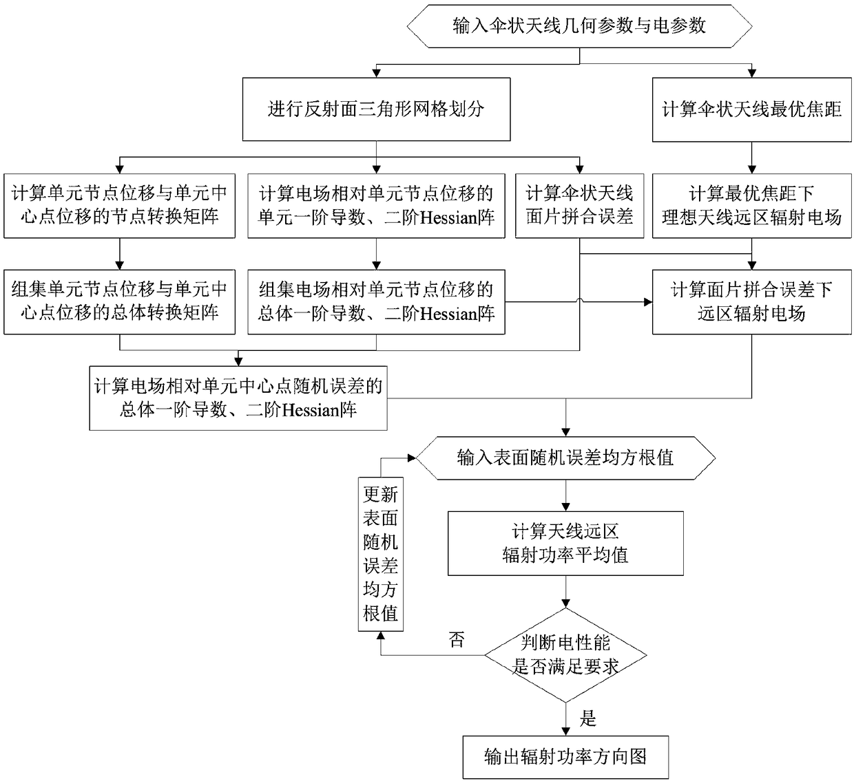
[0078] The method for modeling the average power pattern of an umbrella antenna considering patch stitching errors includes the following steps:

[0079] Step 1, input the geometric parameters and electrical parameters of the umbrella antenna

[0080] Input the geometric parameters and electrical parameters of the umbrella antenna provided by the user; the geometric parameters include aperture, focal length, offset distance and number of ribs; the electrical parameters include operating wavelength, free space wave constant, feed parameters, feed primary pattern, and Electrical performance requirements including antenna gain, lobe width, sidelobe level, and pointing accuracy;

[0081] Step 2, calculate the optimal focal length of the umbrella antenna

[0082] According to the geometric parameters of the antenna provided by the user, the optimal focal length of the umbrella antenna is calculated according to the following formula:

[0083]

[0084] Among them, f s Indicate...

Embodiment 2

[0128] Such as figure 1 As shown, the present invention provides a method for modeling the average power pattern of an umbrella antenna considering patch stitching errors, comprising the following steps:

[0129] Step 1, input the geometric parameters and electrical parameters of the umbrella antenna

[0130] Input the geometric parameters and electrical parameters of the umbrella antenna provided by the user; the geometric parameters include aperture, focal length, offset distance and number of ribs; the electrical parameters include operating wavelength, free space wave constant, feed parameters, feed primary pattern, and Electrical performance requirements including antenna gain, lobe width, sidelobe level, and pointing accuracy;

[0131] Step 2, calculate the optimal focal length of the umbrella antenna

[0132] According to the geometric parameters of the antenna provided by the user, the optimal focal length of the umbrella antenna is calculated according to the follow...


PUM

PropertyMeasurementUnit
Caliberaaaaaaaaaa

Abstract

The invention relates to an umbrella antenna average power pattern modeling method considering surface patch splicing error, which comprises the following steps of: inputting umbrella antenna geometryand electric parameters; the far field of the ideal antenna is calculated under the optimal focal length and the optimal focal length of the umbrella antenna. Reflector triangular mesh generation; the nodal transformation matrix of the patch splicing error and the element node displacement and the element center displacement of the umbrella antenna is calculated. The Overall Transformation Matrixbetween the Node Displacement and the Center Displacement of the Group Element; the first derivative of the element and the second Hessian matrix of the electric field relative to the node displacement of the element are calculated. The global first derivative of the group electric field relative to the node displacement of the element, the second order Hessian matrix; the total first derivativeand second order Hessian matrix of the far field and the random error of the electric field relative to the center point of the element are calculated under the patch splicing error. RMS value of input surface random error; calculating an average value of the far-field radiation power of the antenna; judging whether the electrical performance is satisfied; outputting radiated power pattern; updatingthe surface random error rms value.

Description

technical field [0001] The invention belongs to the technical field of radar antennas, and in particular relates to a method for modeling an average power pattern of umbrella antennas in the field of radar antennas considering patch stitching errors. Background technique [0002] Due to the advantages of simple structure, light weight and low cost, the umbrella antenna is widely used in the field of satellite deployable antenna design. During the manufacturing process of the umbrella antenna components, random errors are inevitably introduced, which leads to the deterioration of its electrical performance; with the increase of the frequency band of the umbrella antenna application, the impact of random errors on the electrical performance of the umbrella antenna is becoming more and more serious. It is a research topic in umbrella antenna design to carry out relevant research on the influence of random errors on the surface of umbrella antennas on its electrical performance,...

Claims


Application Information

Patent Timeline
IPC IPC(8): G06F17/50
CPCG06F30/367
Inventor 张树新张顺吉段宝岩邢永涛韩晓童
Owner XIDIAN UNIV
Why Eureka
Try Eureka