Effluent and drain temperature measurement and calculation method of heater with drain cooler on steam turbine

A hydrophobic cooling and hydrophobic temperature technology, applied in the direction of temperature measurement of moving fluids, can solve the problems of complex installation position, large thermal inertia, and high measurement cost

Inactive Publication Date: 2010-09-08
SOUTHEAST UNIV
View PDF1 Cites 21 Cited by
  • Summary
  • Abstract
  • Description
  • Claims
  • Application Information

AI Technical Summary

Problems solved by technology

[0003] At present, in the thermal power plant's plant-level monitoring information system SIS (Supervisory Information System) or system distributed control system DCS (Distribution Control System), for the regenerative heater with drain cooler, although there are outlet water and drain temperature measuring points , but due to poor operating conditions and poor maintenance, poor measurement reliability is common. In addition, the conventional measurement method of water side temperature of the heater has the following shortcomings: First, in the thermal measurement system of thermal power units, often A thermal resistance sensor is used to monitor the outlet water temperature of the regenerative heater, and the corresponding data acquisitio

Method used


Image

  • Effluent and drain temperature measurement and calculation method of heater with drain cooler on steam turbine
  • Effluent and drain temperature measurement and calculation method of heater with drain cooler on steam turbine
  • Effluent and drain temperature measurement and calculation method of heater with drain cooler on steam turbine

Examples


Embodiment Construction

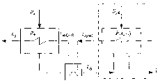
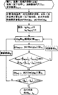
[0073] A method for measuring and calculating the outlet water and drain temperature of a heater with a drain cooler in a steam turbine, characterized in that,

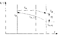
[0074] Step 1: Calculate the intermediate transition point temperature t between the pure condensation section and the hydrophobic cooling section of the heater under the reference condition wn(j+1) o :

[0075] Select the rated load design condition of the unit or the performance assessment test condition as the reference condition, and the parameters with the letter "o" added to the symbol indicate that they are parameters under the reference condition. Parameter: shell side pressure p nj o , shell side extraction enthalpy h nj o , Hydrophobic temperature t dj o , outlet water temperature t wj o , Inlet water temperature t w(j+1) o and unit power P e o , and calculate the shell side pressure p according to the IAPWS-IF97 industrial water and steam thermodynamic properties model nj o The corresponding ...


PUM


Abstract

The invention discloses an effluent and drain temperature measurement and calculation method of a heater with a drain cooler on a steam turbine. The method comprises the following steps: a machine set design condition or a performance test condition is selected as a reference condition; the case side pressure, the case side steam extraction enthalpy, the drain temperature, the effluent temperature, the inflow temperature and the machine set power of the heater under the reference condition are selected to calculate the heat transfer characteristic coefficient of the pure condensation section and the drain cooling section of the heater under the reference condition; the case side pressure, the heater inflow temperature and the machine set power under the actual condition are read or calculated in the database of a monitoring information system SIS or a decentralized control system DCS of a heat-engine plant; the heat transfer characteristic coefficient of the pure condensation section of the heater under the actual condition is calculated by the corresponding heat transfer characteristic coefficient of the pure condensation section of the heater under the reference condition; the actual effluent temperature is obtained by iterative computation; the heat transfer characteristic coefficient of the drain cooling section of the heater under the actual condition is calculated according to the heat transfer characteristic coefficient of the drain cooling section of the heater under the reference condition, and the drain temperature is obtained by iterative computation.

Description

technical field [0001] The invention relates to a method for measuring and calculating the parameters of a heater with a steam turbine with a drain cooler, in particular to a method for measuring and calculating the outlet water and drain temperature of a heater with a drain cooler for a steam turbine. Background technique [0002] With the continuous improvement of the parameters and capacity of thermal power units, improving the performance of the heat recovery system to improve the operating economy of the unit has attracted increasing attention. The measurement of the outlet water and drain temperature of the regenerative heater plays an important role in the calculation of the heat balance of the regenerative system and the monitoring and optimization of unit performance, so it is necessary to monitor it online. So far, there is no report on the calculation method of the outlet water and drain temperature of the heater with drain cooler in the heat recovery system. [...

Claims


Application Information

Patent Timeline
IPC IPC(8): G01K13/02
Inventor 王培红王泉李兵殷捷许寅
Owner SOUTHEAST UNIV
Why Eureka
Try Eureka