
A Flash device erase and writing life testing system device

A life test and system device technology, applied in the direction of instruments, static memory, etc., can solve the problems that the address traversal read operation of storage devices cannot be realized, the low temperature environment cannot be provided, and the initial life of electronic components can be shortened, so as to improve the anti-interference performance , Simplify the power supply input and avoid the effect of temperature shock

Active Publication Date: 2019-03-01
XIAN MICROELECTRONICS TECH INST
View PDF5 Cites 4 Cited by
  • Summary
  • Abstract
  • Description
  • Claims
  • Application Information

AI Technical Summary

Problems solved by technology

Burn-in is mainly used to accelerate and shorten the initial life of electronic components. Therefore, the excitation signal that the burn-in box can output is simple, and it is difficult to provide timing signals for the erasing and writing operations of Flash devices; the address traversal read operation of storage devices cannot be realized. The test coverage of the steady-state life test is incomplete; and the burn-in box cannot provide a low-temperature environment, so the burn-in box cannot be used to complete the erasing and writing fatigue life test of Flash devices
Flash write fatigue test and steady-state life test require the functional operation of the device to be easily realized on a conventional functional test board. For example, the test circuit board is placed in a high and low temperature box for testing. The same test circuit board is subject to the same temperature shock during the test. Even if the quality level of the peripheral auxiliary circuit reaches the military level, it is difficult to guarantee the function of the auxiliary circuit after a round of tests, resulting in the uncertainty of the test circuit board.

Method used


Image

  • A Flash device erase and writing life testing system device
  • A Flash device erase and writing life testing system device

Examples


Embodiment Construction

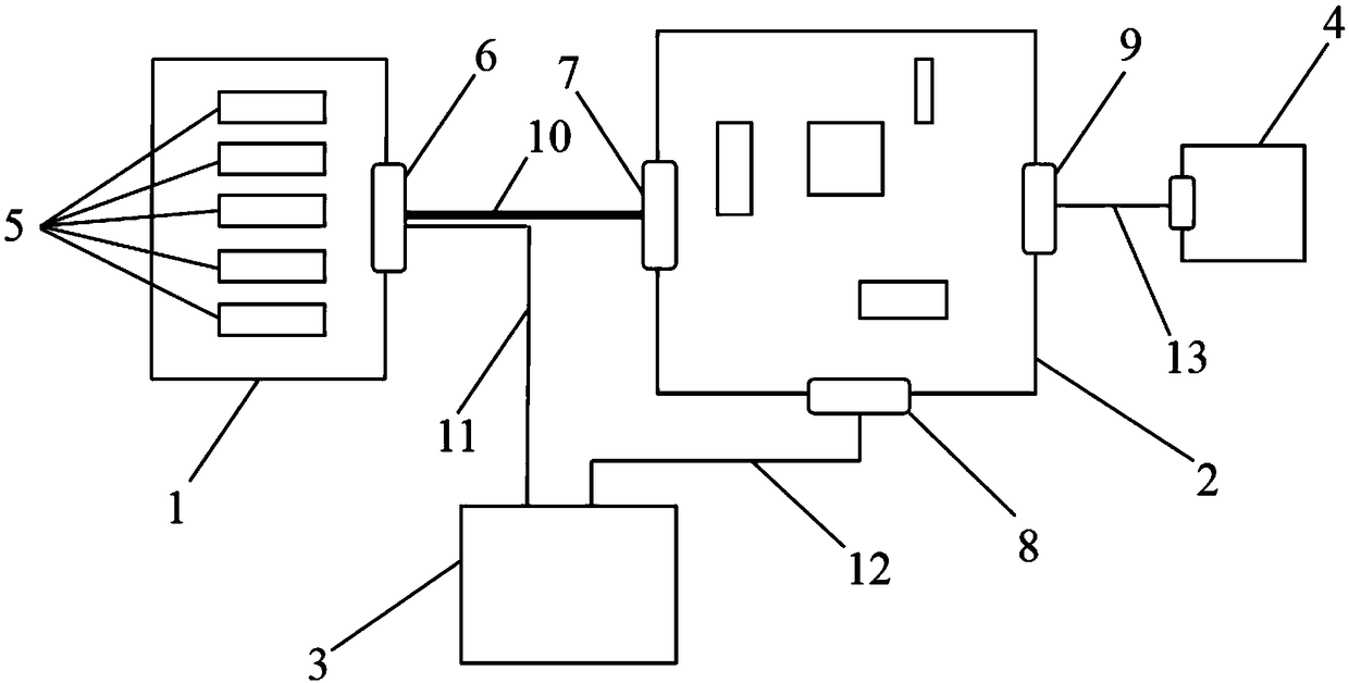
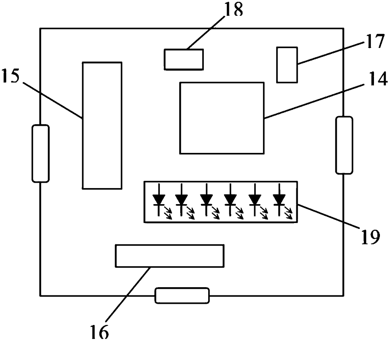
[0033] The invention provides a Flash device erasing and writing life testing system device. The tested device test carrier board for placing the tested Flash device and the test control display circuit board for generating test excitation signals and reading back judgment are two independent circuit boards. Place a corresponding number of test locking sockets on the test carrier board of the device under test according to the requirements of the test for the number of devices under test, so as to ensure good electrical contact between the Flash device under test and the circuit board, and also facilitate the installation of the device; All input and output signal channels are connected to the test carrier board interface socket of the device under test test carrier board through PCB wiring; the device test carrier board is connected to the external power supply line from the interface socket; the test control display circuit board is the core of the test test , all test auxili...


PUM


Abstract

The invention discloses a flash device erasing and writing life testing system device. A test carrier board of a tested device is connected with a PC through a test control display circuit board, anda DC voltage stabilized power supply is connected with the test carrier board of the tested device and the test control display circuit board respectively. A testing locking socket is arranged on thattest carrier board of the device under test. A testing flash device is mounted on that testing lock socket. The test control display panel generates an excitation signal and sends the excitation signal to the tested Flash device, and receives the feedback response of the tested Flash device for judging and displaying. The invention can realize two kinds of reliability tests of flash erasing fatigue and steady-state life, and the cost of the scheme is low.

Description

technical field [0001] The invention belongs to the technical field of integrated circuit quality reliability and consistency testing, and in particular relates to a flash device erasing and writing life testing system device. Background technique [0002] Flash has the advantages of low cost, large storage capacity, fast read and write speed, etc., and occupies an important position in the field of memory. According to the structure, it can be divided into two categories: AND and NOR. NOR Flash can be accessed bit by bit and has the characteristics of high read and write speed, but its bit cost is high and it is not easy to be integrated on a large scale; NAND Flash, as a representative of performance and cost balance, has advantages that other memories do not have, and has been widely used in the military field. application. As the storage density of Flash continues to increase and the cost of bits decreases, its storage reliability continues to decrease. How to ensure th...

Claims


Application Information

Patent Timeline
IPC IPC(8): G11C29/56
CPCG11C29/56016
Inventor 李春张晓敏刘洪卫
Owner XIAN MICROELECTRONICS TECH INST
Learn More