Packaging method of low-temperature vacuum infrared detector

A technology of infrared detectors and packaging methods, which is applied in the direction of semiconductor devices, laser welding equipment, electrical components, etc., to achieve the effects of avoiding temperature shock, prolonging vacuum holding time, and reducing leakage holes

Pending Publication Date: 2022-01-21
云南昆物新跃光电科技有限公司
View PDF0 Cites 0 Cited by
  • Summary
  • Abstract
  • Description
  • Claims
  • Application Information

AI Technical Summary

Problems solved by technology

However, it is not suitable for vacuum low-temperature infrared detectors. During the welding process, it is necessary to solve the technical problems that the detector chips in the vacuum tube should be protected from high temperature shocks and require high-vacuum sealing welding.

Method used


Image

  • Packaging method of low-temperature vacuum infrared detector
  • Packaging method of low-temperature vacuum infrared detector
  • Packaging method of low-temperature vacuum infrared detector

Examples


Embodiment 1

[0041] A packaging method for a vacuum low-temperature infrared detector, the method is suitable for unit HgCdTe infrared detectors.

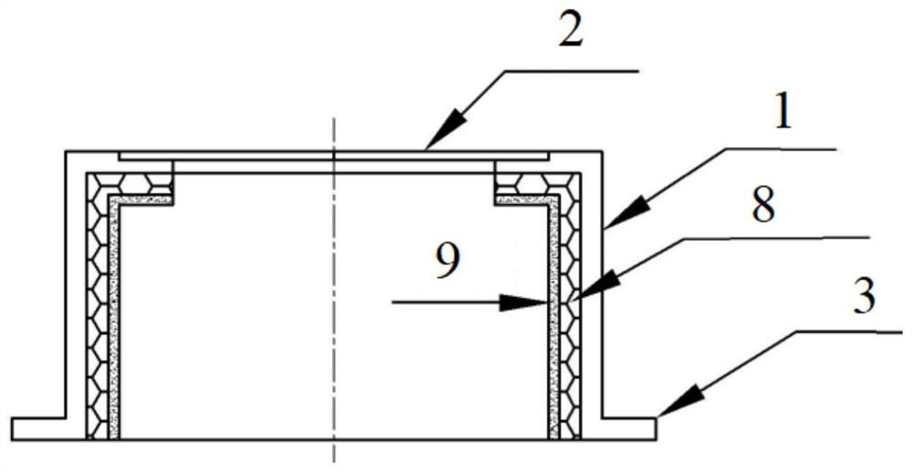
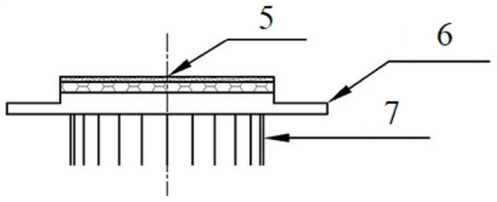
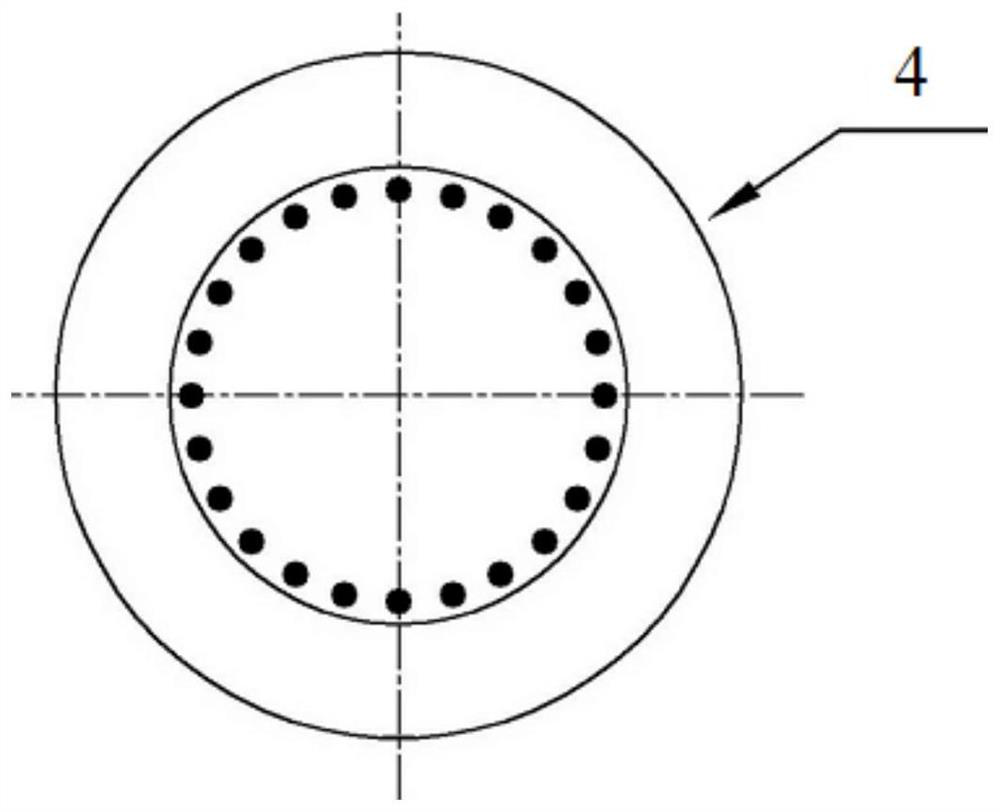
[0042] The method adopts that the vacuum tube encapsulating the infrared detector chip is a cylindrical vacuum tube composed of a stainless steel casing 1 and a Kovar (4J29) base 4 . Such as figure 1 As shown, the housing 1 is a cylinder with a germanium window 2, the outer periphery of the bottom edge of the housing 1 is provided with a housing outer edge 3, the inner space of the housing 1 is used to load an infrared detector chip, and the outer surface of the housing 1 The diameter is 13mm, the wall thickness of the shell 1 is 0.5mm, the height of the shell 1 is 10mm, the diameter of the germanium window 2 is 4.5mm, and the diameter of the outer edge 3 of the shell is 15mm. Such as figure 2 and 3 As shown, the upper surface of the base 4 protrudes as a loading surface 5, and the outer periphery of the bottom of the loading surface 5 of t...

Embodiment 2

[0052] A packaging method for a vacuum low-temperature infrared detector, the method is suitable for unit HgCdTe infrared detectors.

[0053] In the method, the heat-insulating film layer 8 on the inner wall of the vacuum tube shell of the infrared detector chip and the loading surface 5 of the base 4 is replaced with a polyimide film for the aluminum oxide fiber cloth in Example 1, that is, with a polyimide film. The imide solution is bonded with a layer of polyimide film, and is cured by heating according to the curing of polyimide. The polyimide film is DuPont Kapton high temperature resistant PI film with a film thickness of 400 μm. The rest are the same as in Example 1.


PUM

PropertyMeasurementUnit
surface roughnessaaaaaaaaaa
thicknessaaaaaaaaaa
thicknessaaaaaaaaaa

Abstract

The invention relates to a packaging method of a low-temperature vacuum infrared detector, and belongs to the technical field of semiconductors. The method comprises the following steps: polishing the inner surface of a vacuum tube metal shell except a germanium window and a base loading surface; preparing a heat insulation film layer composed of a polyimide layer and an alumina fiber cloth layer on the inner surface and the loading surface; plating a passivation film made of a silicon dioxide or aluminum oxide material on the surface of the heat insulation film layer to form a passivation film layer; and installing an infrared detector chip and a refrigerator on the loading surface, and after electrodes and pins are bonded, carrying out vacuum exhaust and laser fusion welding in a cavity of a vacuum welding workbench so that vacuum sealing packaging is achieved. According to the packaging method, the vacuum sealing of the infrared detector can be realized while the temperature impact on the infrared detector chip caused by a high temperature in the packaging and welding process is avoided; and according to the packaging method, the air output of the inner wall of the vacuum tube after packaging can be effectively reduced, leakage holes in the packaging position of the vacuum tube are effectively reduced, and therefore the vacuum holding time of the low-temperature vacuum infrared detector is prolonged.

Description

technical field [0001] The invention relates to a packaging method for a low-temperature vacuum infrared detector, which belongs to the technical field of semiconductors. Background technique [0002] Infrared detectors of group III-V semiconductor materials represented by InSb (indium antimonide) (hereinafter referred to as InSb infrared detectors) and infrared detectors of group II-VI semiconductor materials represented by HgCdTe (chromium chromium telluride) (hereinafter referred to as HgCdTe infrared detector) is widely used in infrared detection, guidance, homing and thermal imaging. The InSb infrared detector and the HgCdTe infrared detector need to be cryogenically refrigerated (refrigeration temperature should reach 77K±5K) to suppress the thermally generated free carriers that cause noise; at the same time, they also need to work in a vacuum state to improve the infrared The detection sensitivity of the detector. In order to realize the low temperature and vacuum ...

Claims


Application Information

Patent Timeline
Patent Type & Authority Applications(China)
IPC IPC(8): H01L31/18H01L31/0203H01L31/09B23K26/12B23K26/24
CPCH01L31/1832H01L31/184H01L31/1868H01L31/0203H01L31/09B23K26/24B23K26/1224
Inventor 孙祥乐王满良孙茜余连杰孙金鑫戴志军孙金妮余学功太云见闫继娜高立华何燕周春秀黄晖
Owner 云南昆物新跃光电科技有限公司
Why Eureka
Try Eureka