Welding protection device and welding method

A protection device and welding head technology, applied in welding equipment, auxiliary equipment, auxiliary welding equipment, etc., can solve the problems of large consumption of shielding gas and low utilization rate of shielding gas

Active Publication Date: 2022-07-08
WUHAN RAYCUS FIBER LASER TECHNOLOGY CO LTD +1
View PDF6 Cites 0 Cited by
  • Summary
  • Abstract
  • Description
  • Claims
  • Application Information

AI Technical Summary

Problems solved by technology

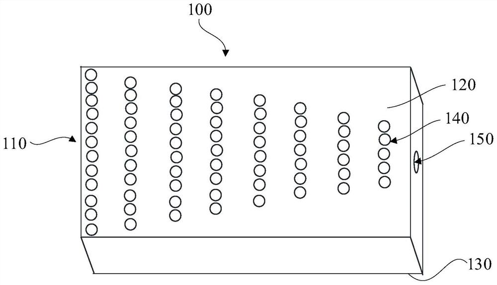
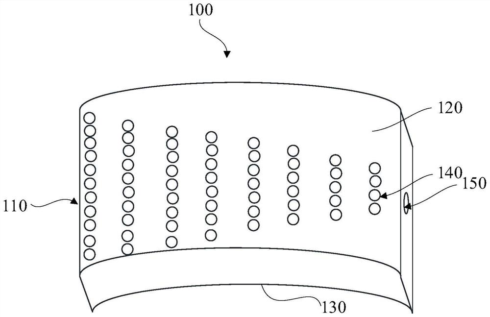
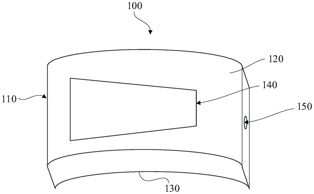
[0003] The embodiment of this application provides a welding protection device and a welding method, aiming to solve the problem that the utilization rate of the shielding gas is low when the back side of the part to be welded is large. The problem of needing to consume a large amount of shielding gas

Method used


Image

  • Welding protection device and welding method
  • Welding protection device and welding method
  • Welding protection device and welding method

Examples


Embodiment Construction

[0036] The technical solutions in the embodiments of the present application will be clearly and completely described below with reference to the accompanying drawings in the embodiments of the present application. Obviously, the described embodiments are only a part of the embodiments of the present application, but not all of the embodiments. Based on the embodiments in this application, all other embodiments obtained by those skilled in the art without creative efforts shall fall within the protection scope of this application.

[0037] In the description of this application, it should be understood that the terms "center", "longitudinal", "lateral", "length", "width", "thickness", "upper", "lower", "front", " rear, left, right, vertical, horizontal, top, bottom, inside, outside, clockwise, counterclockwise, etc., or The positional relationship is based on the orientation or positional relationship shown in the drawings, which is only for the convenience of describing the ...


PUM


Abstract

According to the welding protection device and the welding method, a connecting assembly is connected with a blowing part to adjust the position, relative to the back face of a welding seam, of the blowing part, and the blowing part is driven by the connecting assembly, so that openings, distributed in the first direction, of the blowing part can synchronously move in the moving direction of a welding head; and in the reverse extending direction of the moving direction of the welding head, the air blowing amount of the air blowing piece to all positions of the back face of the welding seam is gradually increased in the moving direction of the welding head. Due to the fact that the temperature of the welding seam is gradually reduced in the reverse extension direction of the moving direction of the welding head, the oxidation reaction activity of the welding seam is gradually reduced along with the reduction of the temperature of the welding seam, and in order to improve the utilization efficiency of the protective gas and save the protective gas, the gas output of the protective gas of the blowing part is gradually reduced in the direction opposite to the first direction. The problems that when the size of the back face of a to-be-welded part is large, the utilization rate of protective gas is low, and a large amount of protective gas needs to be consumed are solved.

Description

technical field [0001] The present application relates to the field of welding technology, and in particular, to a welding protection device and a welding method. Background technique [0002] In the welding process of the existing materials, in order to avoid the oxidation of the material due to the temperature increase during welding, when welding the part to be welded, the protective gas is usually blown out of the front of the part to be welded to prevent the welded part from being oxidized. The back of the welded part will also be oxidized due to the heat conduction of the welding seam. When the size of the back of the part to be welded is large, the existing gas protection device uses a larger size gas protection device to protect the back of the part to be welded. The full coverage of the shielding gas on the back of the part to be welded leads to the current gas shielding device that consumes a lot of shielding gas in order to protect the back of the part to be welde...

Claims


Application Information

Patent Timeline
Patent Type & Authority Applications(China)
IPC IPC(8): B23K37/00
CPCB23K37/00B23K37/003Y02P70/50
Inventor 张衍李陈宾胡晓勇高辉吴泽锋闫大鹏
Owner WUHAN RAYCUS FIBER LASER TECHNOLOGY CO LTD
Why Eureka
Try Eureka