An adaptive multi-stage boost boost chip with automatic current limiting protection function

An automatic current limiting and boosting chip technology, which is applied in the direction of output power conversion device, DC power input conversion to DC power output, instruments, etc., can solve the problem of small output signal amplitude, reduced battery life of portable equipment, and inconformity with green energy saving Environmental protection and other issues to achieve the effect of improving low efficiency

Active Publication Date: 2020-09-01
JIAXING HEROIC ELECTRONICS TECH
View PDF7 Cites 0 Cited by
  • Summary
  • Abstract
  • Description
  • Claims
  • Application Information

AI Technical Summary

Problems solved by technology

However, under most working conditions, the output signal amplitude of the system drive circuit is very small, and the output voltage value of the DCDC boost chip is always at a high voltage, which will lead to low system efficiency, which does not conform to the trend of green energy saving and environmental protection, and is portable The battery life of the device will also be reduced
[0003] Therefore, those skilled in the art are committed to developing a Boost boost chip with an adaptive multi-stage boost and automatic current limiting protection function to overcome the low efficiency problem of using a DCDC boost chip to supply power to the drive circuit on current portable devices.

Method used


Image

  • An adaptive multi-stage boost boost chip with automatic current limiting protection function
  • An adaptive multi-stage boost boost chip with automatic current limiting protection function
  • An adaptive multi-stage boost boost chip with automatic current limiting protection function

Examples


Embodiment Construction

[0033] The following describes several preferred embodiments of the present invention with reference to the accompanying drawings, so as to make the technical content clearer and easier to understand. The present invention can be embodied in many different forms of embodiments, and the protection scope of the present invention is not limited to the embodiments mentioned herein.

[0034]In the drawings, components with the same structure are denoted by the same numerals, and components with similar structures or functions are denoted by similar numerals. The size and thickness of each component shown in the drawings are shown arbitrarily, and the present invention does not limit the size and thickness of each component. In order to make the illustration clearer, the thickness of parts is appropriately exaggerated in some places in the drawings.

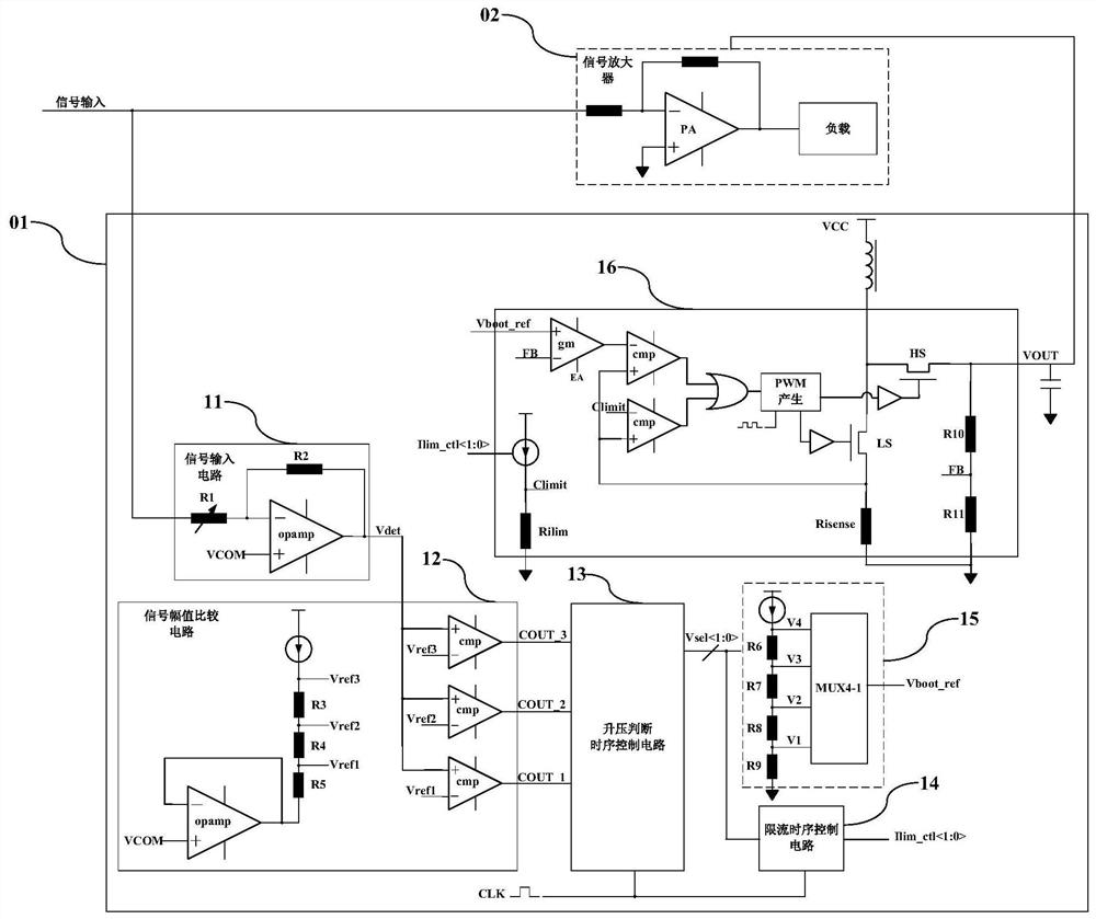
[0035] figure 1 The 01 shown is a block diagram of a DCDC boost chip with real-time monitoring of the input signal envelope of the ...


PUM


Abstract

The invention discloses a self-adaptive multi-section voltage-boosting Boost chip with an automatic current-limiting protection function, and relates to the field of analog integrated circuits. The chip comprises a signal input detection circuit, a signal amplitude comparison circuit a voltage-boosting judgment time sequence control circuit, a current limiting time sequence control circuit, a voltage-boosting gear selection circuit and a voltage-boosting main body circuit. By detecting the amplitude of the envelope of the input signal, the voltage-boosting value is dynamically adjusted in realtime, and the most suitable voltage output in the internally set multi-section voltage value is selected, so that the working efficiency of the system is improved; in addition, during the dynamic switching process of the output voltage value of the DCDC boosted chip, the built-in automatic current-limiting protection function is added, and when it is detected that the system needs to output a voltage value which is higher than the current value, automatic current limiting process intervention is achieved, so that the risk of generating a large surge current when the output voltage is switchedis overcome.

Description

technical field [0001] The invention relates to the field of analog integrated circuits, in particular to a Boost boost chip with self-adaptive multi-stage boost and automatic current limiting protection function. Background technique [0002] In recent years, portable devices have become more and more widely used. Most of these devices are powered by lithium batteries. The maximum voltage of a single lithium battery is 4.2V. Most of the portable devices use a DCDC boost internally to meet the needs of system power supply. Chip to raise the system power supply voltage. Most of the existing solutions are that the DCDC boost chip outputs a fixed voltage. The requirement for this voltage value is: the maximum signal amplitude that can meet the output requirements of the drive circuit in the system. However, under most working conditions, the output signal amplitude of the system drive circuit is very small, and the output voltage value of the DCDC boost chip is always at a hig...

Claims


Application Information

Patent Timeline
Patent Type & Authority Patents(China)
IPC IPC(8): H02M3/157H02M3/158H02M1/32H02M1/44
CPCH02M1/32H02M1/44H02M3/157H02M3/158
Inventor 沈林峰沈世龙卢炜超殷明
Owner JIAXING HEROIC ELECTRONICS TECH
Why Eureka
Try Eureka