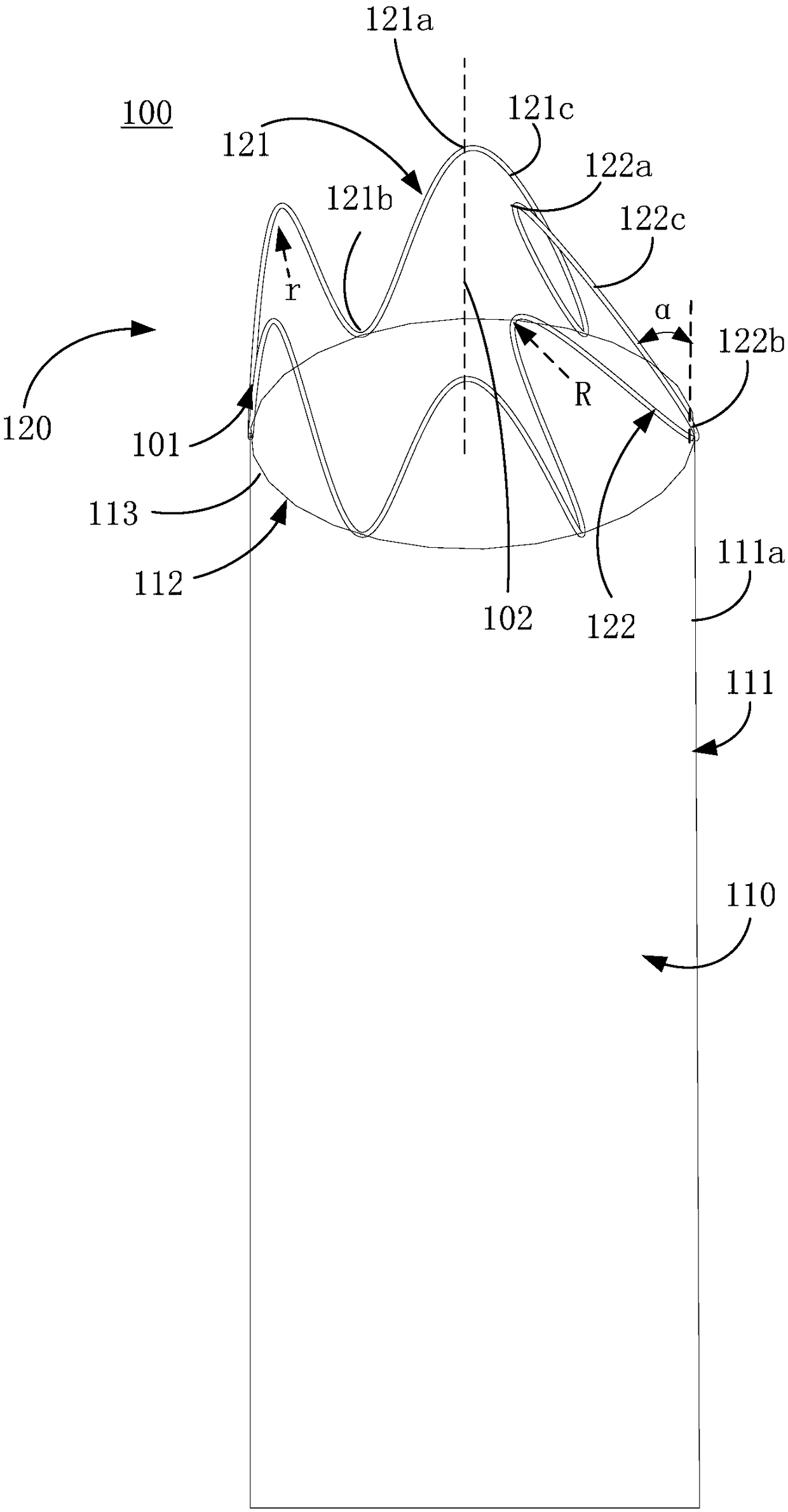
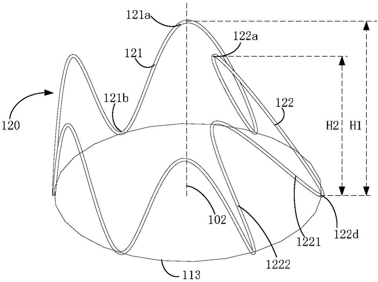
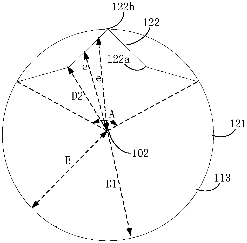
Covered stent
A covered stent and film-covered technology, applied in the field of medical devices, can solve the problems of puncturing branch blood vessels, stimulating and compressing branch blood vessels, and increasing the difficulty of releasing the covered stent, so as to facilitate sheathing and release, avoid stimulation and oppressive effect
- Summary
- Abstract
- Description
- Claims
- Application Information
AI Technical Summary
Problems solved by technology
Method used
Image
Examples
no. 2 example
[0039] refer to Figure 8 and Figure 9 The difference between the stent graft 200 provided by the second embodiment of the present invention and the first embodiment lies in that a connecting piece 205 is connected between the two coils of the stent graft unit 210 disposed close to the exposed unit 220 .
[0040] Specifically, the coating unit 210 includes a first wave coil 203, a second wave coil 204 and a connecting piece 205, the connecting piece 205 extends along the central axis 202 of the coating unit 210, and the first wave coil 203 is closest to the bare unit 220 , the second wave ring 204 is closest to the first wave ring 203 relative to the other wave rings, and one of the inwardly inclined wave bodies 222 occupies a section of arc on the periphery 213 of the end 212 of the coating unit 210 close to the exposed unit 220, on the arc There is a midpoint 2131 that bisects the arc circumferentially. Of course, when the inwardly inclined wave body 222 is an axisymmetri...
no. 3 example
[0046] refer to Figure 10 to Figure 12 The difference between the stent-graft 300 provided by the third embodiment of the present invention and the first embodiment is that the exposed unit 320 further includes a flared corrugated body 323 .
[0047] The flared corrugated body 323 is connected with the upright corrugated body 321 and is arranged on the periphery 313 of the end 312 of the covering unit 310 away from the exposed unit 320, and the flared corrugated body 323 faces away from the central axis 302 of the covering unit 310 from the curved surface 311. Direction tilt (outward tilt) sets the angle β. The flared corrugated body 323 is used to be installed on the lesser curved side 12 of the arterial vessel 10 (see Figure 4 ), that is, the outward tilting wave body 323 is arranged opposite to the inward tilting wave body 322 installed at the greater curvature side 11 of the arterial vessel 10 . Since the outward tilting corrugated body 323 tilts outward to set the ang...
no. 4 example
[0053] refer to Figure 13 The difference between the stent graft 400 provided by the fourth embodiment of the present invention and the third embodiment lies in that the upright corrugated body 421 has an asymmetric shape.
[0054] Specifically, the second wave rod 421c includes a third connecting section 4211 and a fourth connecting section 4212 connected at the second crest 421a, and is close to the second trough on the third connecting section 4211 in the circumferential direction of the stent-graft 400 The apex of 421b is close to the inclination wave body 422, and the apex close to the second trough 421b on the fourth connection section 4212 is away from the inversion wave body 422, that is, close to the outward inclination wave body 423, and the length of the third connection section 4211 is greater than that of the fourth connection section The length of 4212.
[0055] Compared with the length of the third connecting section 4211 equal to the length of the fourth conn...
PUM
 Abstract
Description
Claims
Application Information
 - R&D Engineer
- R&D Manager
- IP Professional
- Industry Leading Data Capabilities
- Powerful AI technology
- Patent DNA Extraction
Browse by: Latest US Patents, China's latest patents, Technical Efficacy Thesaurus, Application Domain, Technology Topic, Popular Technical Reports.
© 2024 PatSnap. All rights reserved.Legal|Privacy policy|Modern Slavery Act Transparency Statement|Sitemap|About US| Contact US: help@patsnap.com


