
Continuous organic waste gas catalytic purification device and running method thereof

A technology for organic waste gas and catalytic purification, applied in chemical instruments and methods, combustion methods, separation methods, etc., can solve the problems of low concentration of organic pollutants, incombustibility, unsuitable for organic waste gas, etc. Effect

Pending Publication Date: 2019-03-08
江嗣中
View PDF0 Cites 0 Cited by
  • Summary
  • Abstract
  • Description
  • Claims
  • Application Information

AI Technical Summary

Problems solved by technology

[0004] However, limited by the combustion conditions of organic waste gas, that is, the concentration of organic pollutants is too low to be combusted, so the above scheme is only suitable for the treatment of high-concentration organic waste gas, and there is a problem that it is not suitable for low-concentration organic waste gas; therefore, it is necessary to propose A new solution to this problem

Method used


Image

  • Continuous organic waste gas catalytic purification device and running method thereof
  • Continuous organic waste gas catalytic purification device and running method thereof
  • Continuous organic waste gas catalytic purification device and running method thereof

Examples


Embodiment 1

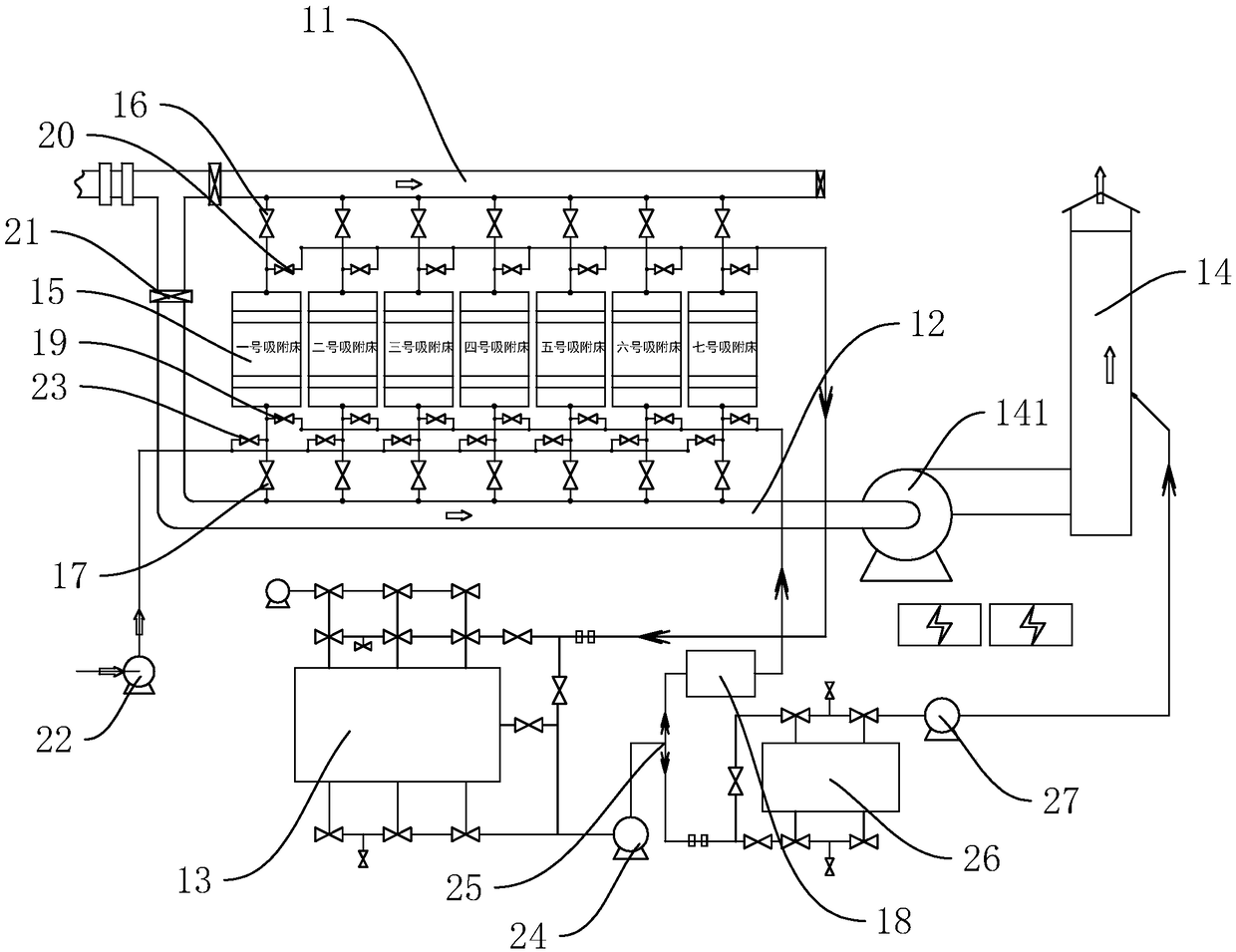
[0026] Embodiment 1: Continuous organic waste gas catalytic purification device, such as figure 1As shown, it includes an intake pipe 11, an exhaust pipe 12, a primary catalytic combustion device 13 and a smoke exhaust pipe 14 connected to the outlet of the exhaust pipe 12, and also includes at least five adsorption beds 15. The specific number of adsorption beds 15 in this embodiment It is seven, wherein, exhaust pipe 14 is provided with power and is the general blower fan 141 of 160kw, and adsorption bed 15 entrances are communicated with inlet pipe 11, and are provided with air intake valve 16, and adsorption bed 15 outlets are communicated with exhaust pipe 12, And be provided with outlet valve 17; Also comprise heater 18, heater 18 is communicated with the outlet end of adsorption bed 15, and between each adsorption bed 15, be respectively provided with heating valve 19, the intake air of primary catalytic combustion device 13 The end communicates with the inlet end of th...

Embodiment 2

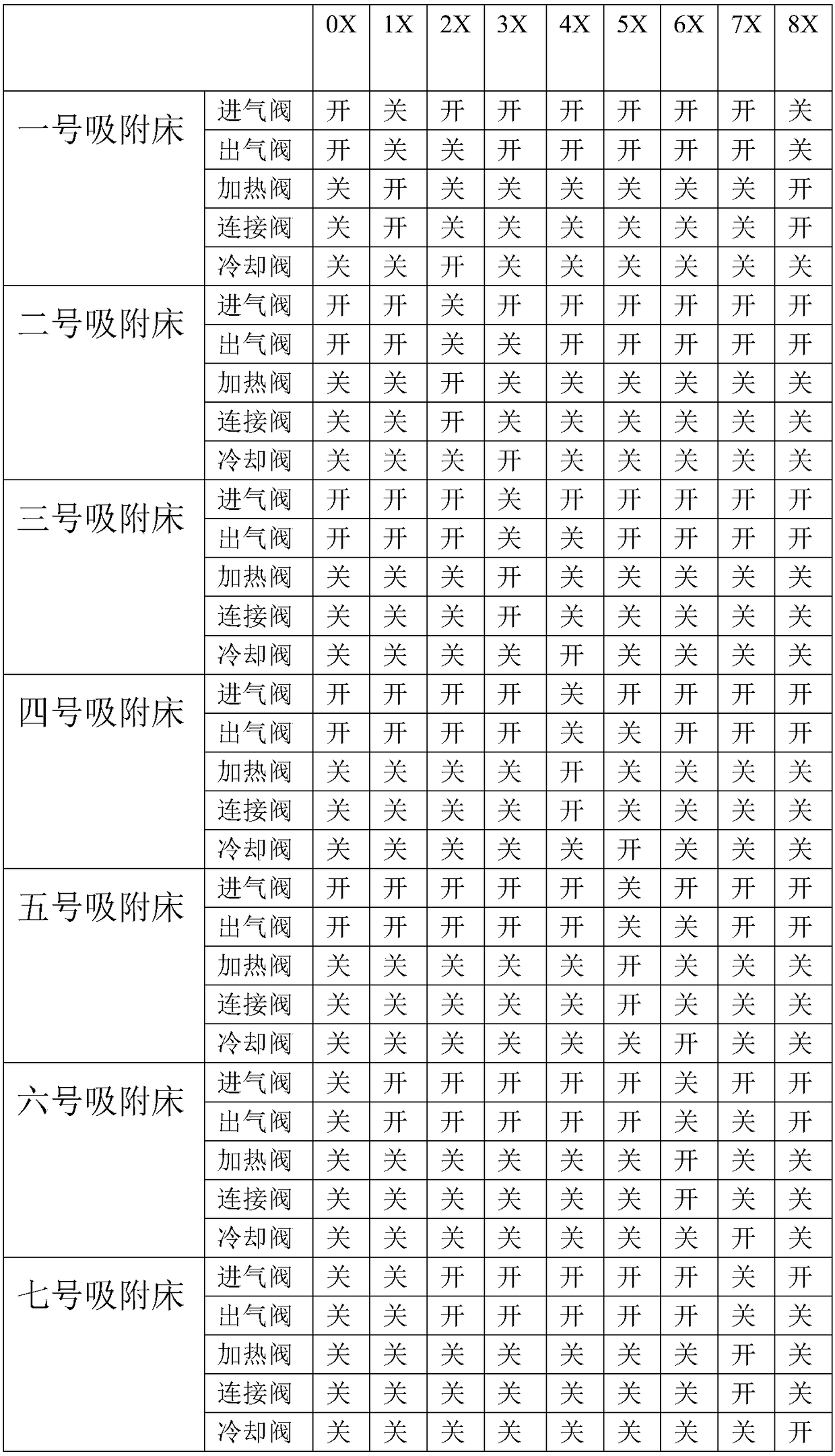
[0032] Embodiment 2: The operation method of the continuous organic waste gas catalytic purification device, such as figure 1 As shown, the specific number of adsorption beds 15 is limited to seven, which are respectively No. 1 adsorption bed, No. 2 adsorption bed, No. 3 adsorption bed, No. 4 adsorption bed, No. 5 adsorption bed, No. 6 adsorption bed, and No. 7 adsorption bed No. adsorption bed, set three operation modes respectively for seven adsorption beds 15, three operation modes are adsorption mode, desorption mode and cooling mode respectively; In the open state, the heating valve 19, the connecting valve 20 and the cooling valve 23 are in the closed state; in the desorption mode, the inlet valve 16, the outlet valve 17 and the cooling valve 23 of the adsorption bed 15 are in the closed state, and the heating valve 19, the connecting valve 20 is in the open state; the cooling mode is that the cooling valve 23 and the inlet valve 16 of the adsorption bed 15 are in the op...


PUM


Abstract

The invention discloses a continuous organic waste gas catalytic purification device and a running method thereof, relates to a waste gas treatment technology, and aims to solve the problem that the prior art is not suitable for low-concentration organic waste gas. The continuous organic waste gas catalytic purification device is characterized by comprising an air inlet pipe, an exhaust pipe, a primary catalytic combustion device, a smoke exhaust barrel, at least five adsorption beds and a heater, wherein the adsorption beds are communicated with the air inlet pipe, and are provided with air inlet valves; the adsorption beds are communicated with the exhaust pipe, and are provided with air outlet valves; the heater is communicated with the adsorption beds, and heating valves are arranged between the heater and each adsorption bed respectively; the primary catalytic combustion device is communicated with the adsorption beds, and connection valves are arranged between the primary catalytic combustion device and each adsorption bed respectively; and the air outlet end of the primary catalytic combustion device is communicated with the smoke exhaust barrel. The continuous organic wastegas catalytic purification device disclosed by the invention can not only be suitable for treating the low-concentration organic waste gas, but improve the purifying effect of high-concentration organic waste gas.

Description

technical field [0001] The invention relates to waste gas treatment technology, more specifically, it relates to a continuous organic waste gas catalytic purification device and its operating method. Background technique [0002] Regenerative catalytic combustion method (also known as RCO) is an effective organic waste gas treatment method, and it is also an internationally recognized energy-saving organic waste gas treatment device, especially suitable for adsorption and desorption of high-concentration organic waste gas; its working characteristics are : Raise the waste gas containing high concentration of organic solvent to a certain temperature, and use catalyst to make the organic waste gas burn without flame at a lower light-off temperature, and oxidize and decompose into CO2 and H2O, and release a lot of heat energy at the same time. [0003] At present, the commonly used catalytic combustion device consists of a four-way reversing valve and two catalytic combustion b...

Claims


Application Information

Patent Timeline
IPC IPC(8): B01D53/02F23G7/07
CPCB01D53/02F23G7/07B01D2257/70B01D2259/4063B01D2259/40088B01D2253/102
Inventor 江嗣中
Owner 江嗣中
Learn More