Cutter wheel connecting sliding table for vertical hub spinning machine

A spinning machine and sliding table technology, which is applied in the field of connecting the sliding table with the cutter wheel of the vertical hub spinning machine, can solve the problems of inability to rotate at an angle, small contact area under force, and limited output force of the cutter wheel, etc., to achieve Improve the transmission stiffness, increase the transmission contact surface, and prevent offset effects

Inactive Publication Date: 2019-03-08
广东博赛数控机床有限公司
View PDF0 Cites 0 Cited by
  • Summary
  • Abstract
  • Description
  • Claims
  • Application Information

AI Technical Summary

Problems solved by technology

Most of the existing connecting slides use linear guide rail slides. However, linear guide rail slides use multi-faceted positioning and force, and their force contact area is small. Although the positioning is accurate, the stability is average.
And in the linear guide rail slide table, the linear guide rail can only drive the slide table to move in a straight line, and cannot perform angular rotation; if the angle change needs to be increased, additional angle adjustment mechanism components are required, which makes the structure complicated and the production cost also increased
Moreover, when the cutter wheel is adjusted and positioned, due to the increase of the spinning pressure, it is easy to appear that the cutter wheel positioning is uncontrollable and the output force of the cutter wheel is limited by the transmission system.

Method used


Image

  • Cutter wheel connecting sliding table for vertical hub spinning machine
  • Cutter wheel connecting sliding table for vertical hub spinning machine

Examples


Embodiment 1

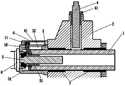
[0033] A vertical hub spinning machine uses a cutter wheel to connect the slide table, and its cross-sectional structure schematic diagram is as follows figure 1 As shown, it includes an X-axis sliding table 1 , a Z-axis sliding table 2 , an anti-rotation adjustment connecting seat 3 , a Z-axis screw rod 4 and an X-axis screw rod 5 . Wherein, the interior of the X-axis sliding table 1 is hollow, and the X-axis sliding table 1 is arranged through the Z-axis sliding table 2, and the X-axis sliding table 1 and the Z-axis sliding table are vertically arranged. And specifically, the X-axis sliding table 1 is installed with the Z-axis sliding table 2 through more than two graphite bearings 7, so as to be installed on the Z-axis sliding table 2, and the X-axis sliding table 1 can pass through the graphite bearing 7 on the X-axis. Axis direction movement. In this embodiment, there are two graphite bearings 7 . The X-axis sliding table 1 is set in the Z-axis sliding table 2. When the...

Embodiment 2

[0046] A cutter wheel connecting slide table for a vertical hub spinning machine, similar to Embodiment 1, the difference is that the anti-rotation adjustment connection seat 3 is not fixedly connected with the Z-axis slide table 2 through screws, but the anti-rotation adjustment connection seat 3 A first gear (not shown) is fixedly installed on the outer surface near the reducer connection seat 8 or near the end of the Z-axis slide table 2; and the first gear meshes with the second gear (not shown), and the second The gear is connected to the output end of the second servo motor (not shown) with a reducer, and the second servo motor is controlled by the system, so that the rotation of the X-axis sliding table can be adjusted directly through the system, and the rotation angle is controlled by the system, reducing labor The operation error and cost make the angle rotation adjustment of the overall connection slide table structure more convenient and more flexible in processing....


PUM


Abstract

The invention discloses a cutter wheel connecting sliding table for a vertical hub spinning machine. The connecting sliding table comprises an X-axis sliding table (1), a Z-axis sliding table (2), ananti-rotation adjusting connecting base (3), a Z-axis screw rod (4) and an X-axis screw rod (5), wherein the Z-axis screw rod (4) and the X-axis screw rod (5) are perpendicular to each other; the X-axis sliding table (1) is arranged in the Z-axis sliding table (2) in a penetrating mode; one end of the X-axis sliding table (1) is fixedly connected with an X-axis screw rod nut (51) matched with theX-axis screw rod (5); one end of the X-axis screw rod (5) is installed on the anti-rotation adjusting connecting base (3), and the other end of the X-axis screw rod (5) extends into the X-axis slidingtable (1); and the Z-axis screw rod (4) is installed in the Z-axis sliding table (2), and an anti-rotation adjusting connecting base (3) is further provided with an anti-rotation adjusting groove (32) and an anti-rotation block (10). The connecting sliding table can realize accurate adjustment of the position state of a cutter wheel by a driving mechanism, the action conduction sensitivity is high, the positioning and fixing of the cutter wheel can be controlled, and the overall sliding table structure is good in working performance.

Description

technical field [0001] The invention relates to the technical field of slide tables, in particular to a slide table connected with a cutter wheel for a vertical hub spinning machine. Background technique [0002] As a special forming method, spinning is to fix the flat or hollow blank on the mold of the spinning machine, while the blank is rotating with the main shaft of the machine, press the blank with a spinning wheel or a driving rod to produce local plastic deformation. . Under the joint action of the feed motion of the rotary wheel and the rotation motion of the blank, the local plastic deformation is gradually extended to the entire surface of the blank, and it is closely attached to the mold to complete the spinning process of the part. Through spinning, deep drawing, flanging, shrinking, bulging and curling of rotating bodies of various shapes can be completed. Using spinning forming, the equipment and mold are simple, and a small deformation force can form a larg...

Claims


Application Information

Patent Timeline
IPC IPC(8): B21D22/14
Inventor 周路周平虎童兆军黄晓楚冯诗荣苏伟杰
Owner 广东博赛数控机床有限公司
Why Eureka
Try Eureka