Floor type chain link disassembling and assembling machine

A dismounting machine, floor-standing technology, applied in the direction of metal chains, etc., can solve the problems of difficult fixing of adjacent two chain links, long working time, inaccurate pin hole alignment, etc., to meet the needs of field operations, installation and Easy operation, simple structure and compact effect

Pending Publication Date: 2019-03-08
QUANZHOU HUAMAO MACHINERY EQUIP
View PDF0 Cites 2 Cited by
  • Summary
  • Abstract
  • Description
  • Claims
  • Application Information

AI Technical Summary

Problems solved by technology

Manually knocking the chain pins directly with copper rods and hand hammers will often cause damage to the chain pins or the chain pins will collapse, and there is also a great potential safety hazard
The whole disassembly and installation takes a long time, labor intensity is high, and the effect is poor
In addition, when assembling the chain pins, it is difficult to fix the two adjacent chain links, which leads to the inaccurate alignment of the pin holes on the two adjacent chain links, which makes the assembly resistance of the chain pins relatively large, and forced installation may easily cause hidden damage to the chain pins. Or two adjacent links are broken
In the prior art, there is no better tool for chain link dismounting

Method used


Image

  • Floor type chain link disassembling and assembling machine
  • Floor type chain link disassembling and assembling machine
  • Floor type chain link disassembling and assembling machine

Examples


Embodiment Construction

[0024] In order to further explain the technical solution of the present invention, the present invention will be described in detail below through specific examples.

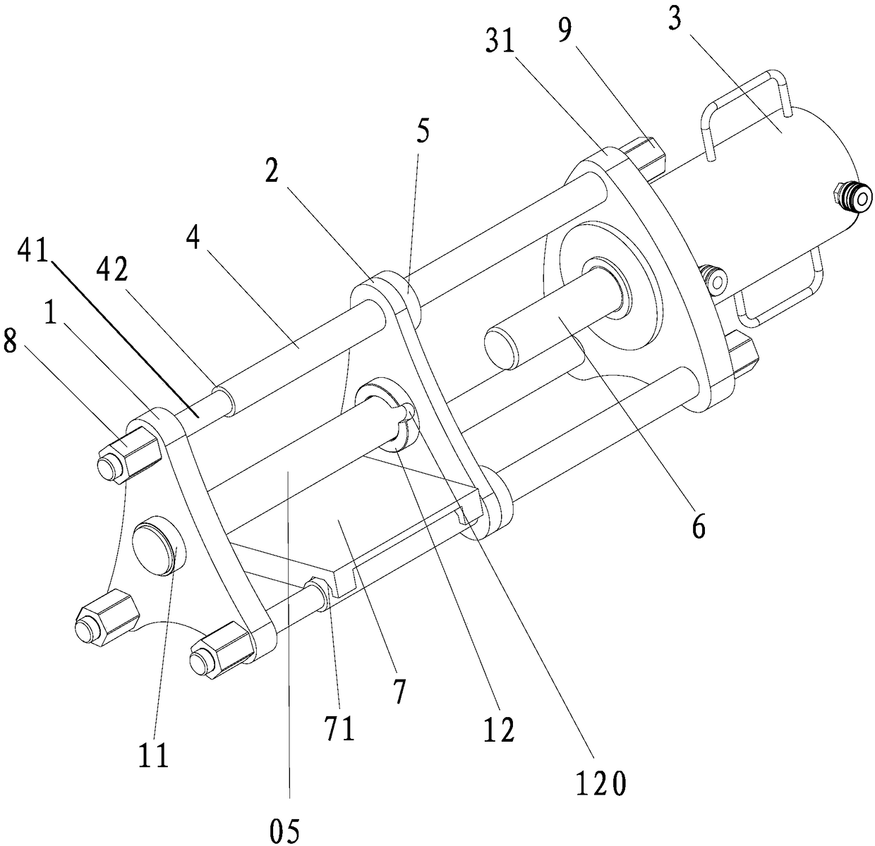
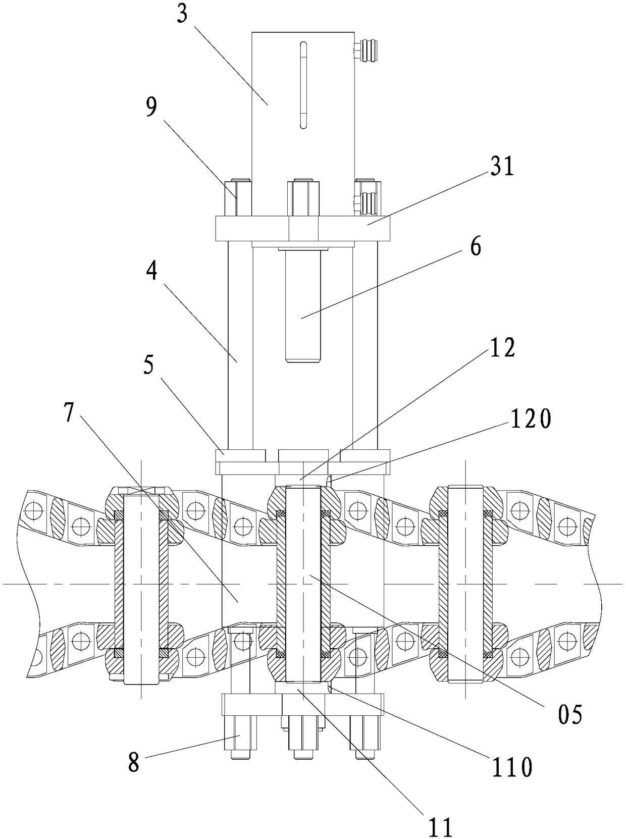
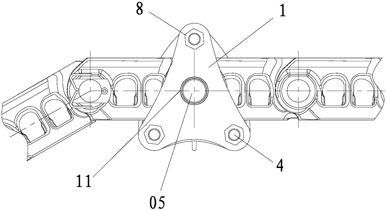
[0025] Such as Figure 1-3 As shown, the floor type chain link dismounting machine of the present invention includes an adjusting plate 1, a supporting plate 2 and an oil jack 3 with a bottom plate 31, and the supporting plate 2 is located between the adjusting plate 1 and the oil jack 3 In between, the adjusting plate 1 is connected to the bottom plate 31 of the hydraulic jack 3 through at least three parallel connecting rods 4, the adjusting plate 1 is detachably connected to the connecting rods 4, the hydraulic jack The bottom plate 31 of the jack is connected to the connecting rod 4 in a detachable manner; The fixed ring 5 for limiting the sliding stroke (specifically: the fixed ring 5 and the connecting rod 4 are integrally formed), the plunger of the hydraulic jack faces the support plate 2, and the hydr...


PUM


Abstract

The invention discloses a floor type chain link disassembling and assembling machine. The floor type chain link disassembling and assembling machine comprises an adjusting plate, a supporting plate and an oil jack provided with a bottom plate. The supporting plate is located between the adjusting plate and the oil jack. The adjusting plate is connected with the bottom plate of the oil jack throughat least three parallel link rods. The adjusting plate is detachably connected with the link rods. The bottom plate of the oil jack is detachably connected with the link rods. The supporting plate isslidably arranged on the link rod in a sleeving mode. Each link rod is provided with a fixed ring. A plunger of the oil jack faces the supporting plate. A press-fitting pad rod is mounted on the plunger of the oil jack. The adjusting plate is provided with a first through hole. The supporting plate is provided with a second through hole. A working platform is arranged between the adjusting plateand the supporting plate. The floor type chain link disassembling and assembling machine provided by the invention is simple in structure, convenient to use, high in disassembling and assembling efficiency, capable of saving more time and labor, safer in use and also capable of effectively protecting chain links against deformation in the disassembling and assembling process.

Description

technical field [0001] The invention relates to the technical field of mechanical equipment, in particular to a floor-mounted chain link dismantling machine. Background technique [0002] Traditional heavy machinery crawlers are generally assembled manually. During assembly, the chain pins are usually aligned with the chain pins by hand with copper rods and hand hammers, and the chain pins are driven into the pin holes of the two adjacent chain links one by one to complete the assembly of the track. When disassembling, also use the same method to punch out the chain pin. Manually knocking the chain pins directly with copper rods and hand hammers often causes damage to the chain pins or the phenomenon of chain pin chipping, and there is also a great potential safety hazard. The whole dismantling and installation cost a long working time, high labor intensity and poor effect. In addition, when assembling the chain pins, it is difficult to fix the two adjacent chain links, w...

Claims


Application Information

Patent Timeline
Patent Type & Authority Applications(China)
IPC IPC(8): B21L9/06
CPCB21L9/065
Inventor 杨春锦甘训利
Owner QUANZHOU HUAMAO MACHINERY EQUIP
Why Eureka
Try Eureka