Combined press

A technology of presses and unions, which is applied in the field of hydraulic presses, can solve the problems of large distance between equipment and equipment, increase the occupied area, and large occupied area, and achieve the effect of compact structure, reduced occupied area and good rigidity

Pending Publication Date: 2019-03-08
CHONGQING JIANGDONG MACHINERY
View PDF6 Cites 0 Cited by
  • Summary
  • Abstract
  • Description
  • Claims
  • Application Information

AI Technical Summary

Problems solved by technology

[0002] The existing cup-shaped or barrel-shaped parts that are similar to the back cover and have a certain wall thickness are often completed in the forming process by upsetting, punching, and drawing, while upsetting uses upsetting equipment, and punching uses punching Equipment, drawing equipment is used for drawing, and various equipments are jointly produced to form a production line, but at present, there are more and more equipment in the processing plant, and the equipment is getting larger and larger, resulting in an increasing area of ​​​​occupancy, and the equipment and The distance between the equipment is large, and the products need to be transported at a certain distance, which further increases the occupied area and increases the cost

Method used


Image

  • Combined press
  • Combined press

Examples


Embodiment

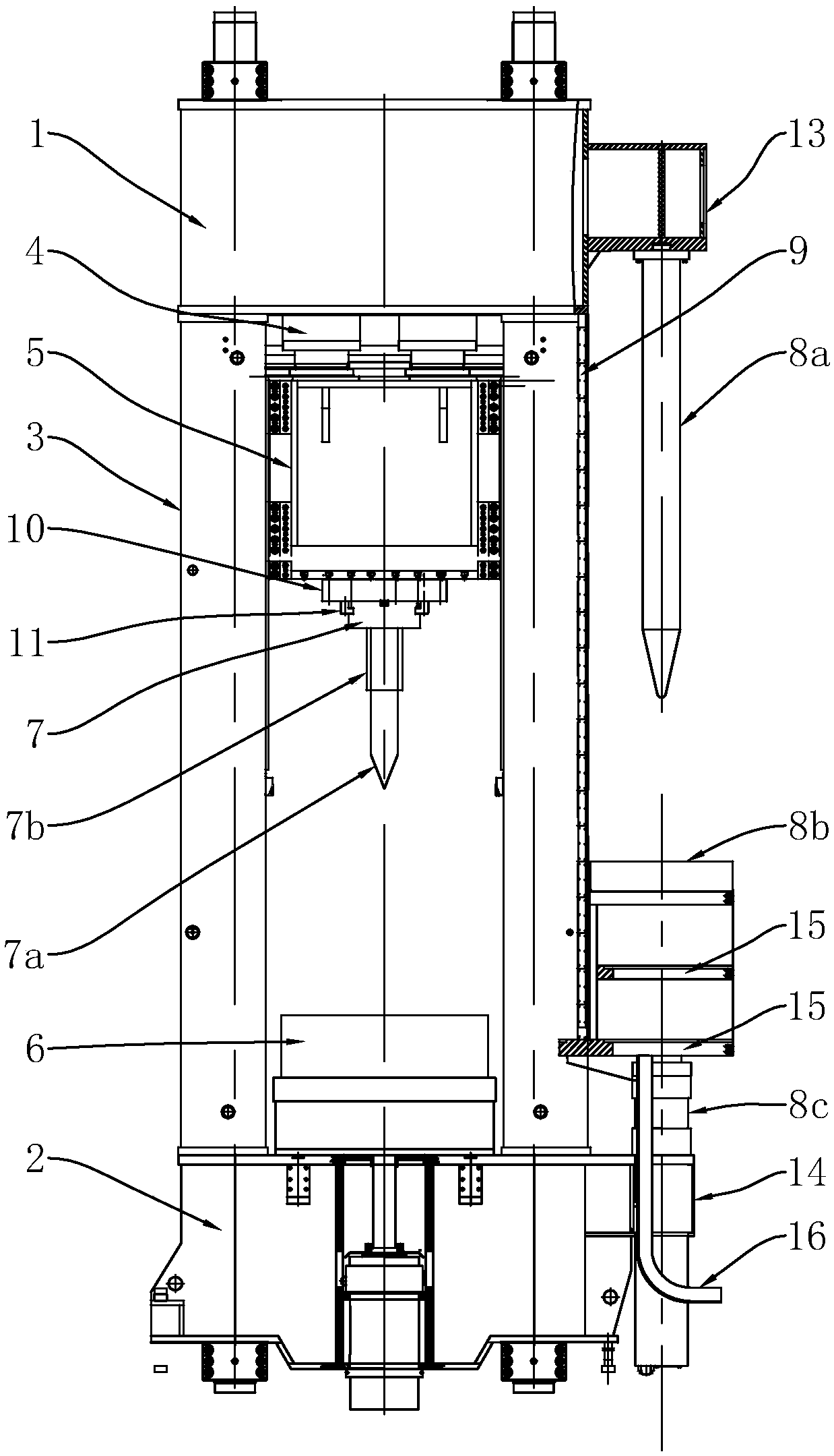
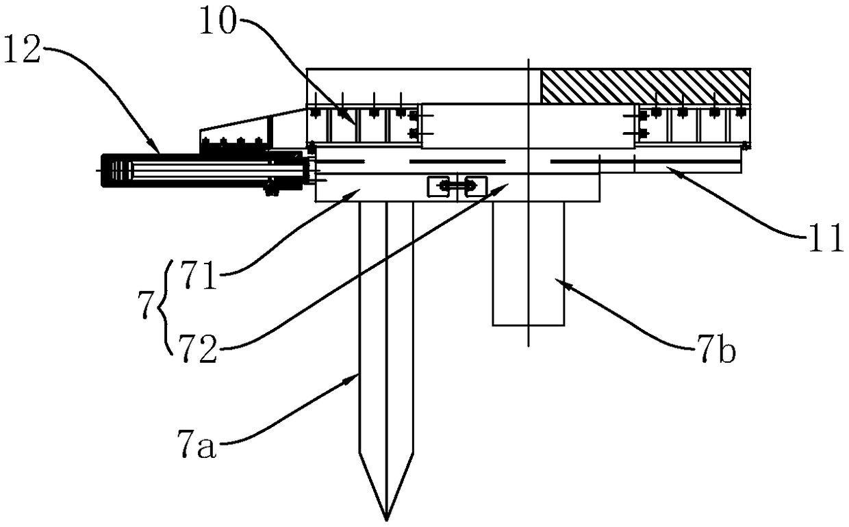
[0024] Such as figure 1 and 2 Shown: a combination press, consisting of an upper beam 1, a lower beam 2, a column 3, a main cylinder 4, a punching slider 5, a lower die 6 and a drawing device, the upper beam 1, the lower beam 2 , columns 3 are combined to form a frame, the columns 3 are arranged in a rectangle and fixed vertically on the lower beam 2, the upper beam 1 is fixed on the top of the column 3, and the master cylinder 4 is located on the On the upper beam 1, the lower piston rod end of the master cylinder 4 is fixedly connected to the top of the punching slider 5, the punching slider 5 is slidably arranged between the columns 3, and the lower mold 6 is fixedly arranged On the lower beam 2, the lower end surface of the punching slider 5 is fixed with a spacer 10, and the spacer 10 is fixed with a composite slide rail 11, and the position between the two tracks of the composite slide rail 11 is limited. Sliding is provided with a double-station slide table 7, and one...


PUM


Abstract

The invention discloses a combined press. The combined press comprises an upper transverse beam, a lower transverse beam, vertical columns, a main cylinder, a punching slide block and a lower die; theupper transverse beam, the lower transverse beam and the vertical columns are combined to form a rack, a double-station sliding table is slidably arranged at the lower end of the punching slide block, the sliding table is provided with a punching punch and an upsetting punch, a pulling-extending device is arranged on one side of the rack, and the pulling-extending device comprises a pulling-extending punch, a pulling-extending slide block and a pushing cylinder; and the pulling-extending punch is longitudinally and fixedly mounted on the outer side of the upper transverse beam, the pulling-extending slide block is arranged under the pulling-extending punch, longitudinal guide rails are arrange on the two adjacent vertical columns on the corresponding sides, the two ends of the pulling-extending slide block are arranged on the vertical columns in limiting and sliding modes through the two corresponding sliding rails correspondingly, the lower end of the pulling-extending slide block isfixedly connected with the pushing cylinder, and the pushing cylinder is longitudinally mounted on the lower transverse beam. The combined press can complete three processes of upsetting, punching and pulling-extending, a mechanism is simplified, the cost is saved, the transferring distance is greatly shortened, and the occupied area of the equipment is decreased.

Description

technical field [0001] The invention belongs to the technical field of hydraulic presses, and in particular relates to a combination press. Background technique [0002] The existing cup-shaped or barrel-shaped parts that are similar to the back cover and have a certain wall thickness are often completed by upsetting, punching, and drawing in the forming process, while upsetting equipment is used for upsetting, and punching is used for punching. Equipment, drawing equipment is used for drawing, and each equipment is jointly produced to form a production line, but at present, there are more and more equipment in the processing plant, and the equipment is also getting larger and larger, resulting in a larger and larger floor area, and the equipment and The distance between the equipment is large, and the products need to be transported at a certain distance, which further increases the occupied area and increases the cost. Contents of the invention [0003] In order to solv...

Claims


Application Information

Patent Timeline
Patent Type & Authority Applications(China)
IPC IPC(8): B23P23/00
CPCB23P23/00
Inventor 胥筱康向代忠刘雪飞汪义高凌家友蒋小龙梁先勇程国庆
Owner CHONGQING JIANGDONG MACHINERY
Why Eureka
Try Eureka