
Railway vehicle primary suspension structure and bogie with the same

A railway vehicle and frame technology, which is applied in the directions of bogie, railway body parts, axle box installation, etc., can solve the problems of excessive change in the height difference of the empty-heavy vehicle and the height change of the floor surface of the car body, etc., and achieves low structural cost. , large bearing capacity, and the effect of improving the critical speed of serpentine instability

Pending Publication Date: 2019-03-08
CRRC CHANGCHUN RAILWAY VEHICLES CO LTD
View PDF0 Cites 0 Cited by
  • Summary
  • Abstract
  • Description
  • Claims
  • Application Information

AI Technical Summary

Problems solved by technology

[0004] The purpose of the present invention is to provide a new type of primary suspension structure of railway vehicles, which can reduce the difference in height variation of the car body floor surface under the working condition of empty and heavy vehicles, and solve the problem that the primary suspension rigidity of rail vehicles needs to meet the critical speed and the height difference of empty and heavy vehicles The paradox of changing too much

Method used


Image

  • Railway vehicle primary suspension structure and bogie with the same
  • Railway vehicle primary suspension structure and bogie with the same
  • Railway vehicle primary suspension structure and bogie with the same

Examples


Embodiment Construction

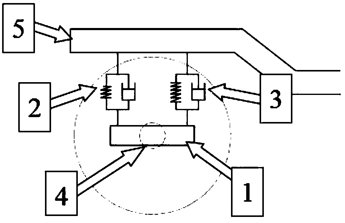
[0012] refer to figure 1 The present invention adopts a steel spring structure 2 on the outside of the axle 4, and a rubber spring structure 3 on the inside of the axle. The front end of the protruding part below the side beam of the frame is also fixed on the axle box 1 below, connected through the axle box structure, and carries a series of suspended vertical loads in parallel, and the lateral and longitudinal rigidity is provided by rubber springs.

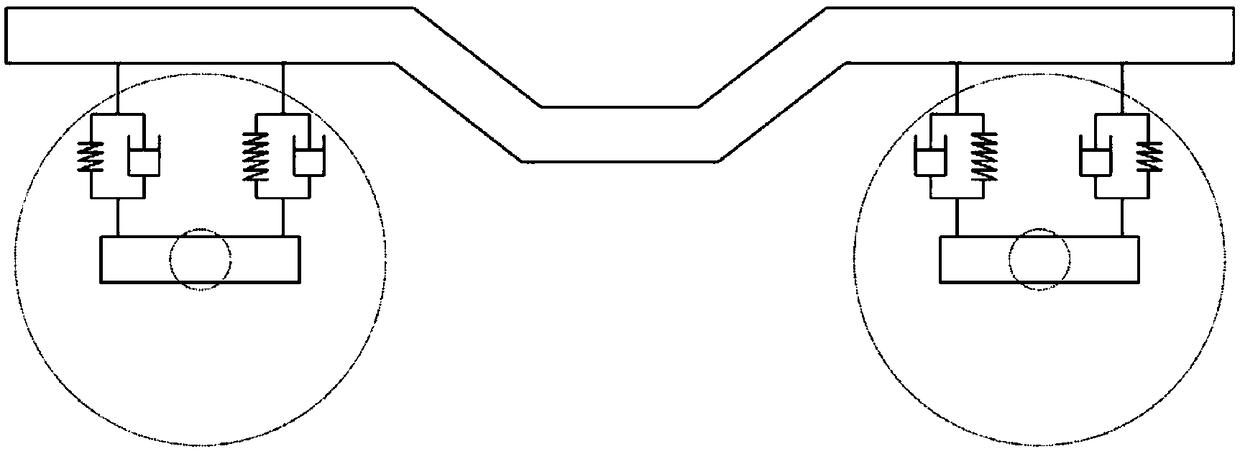
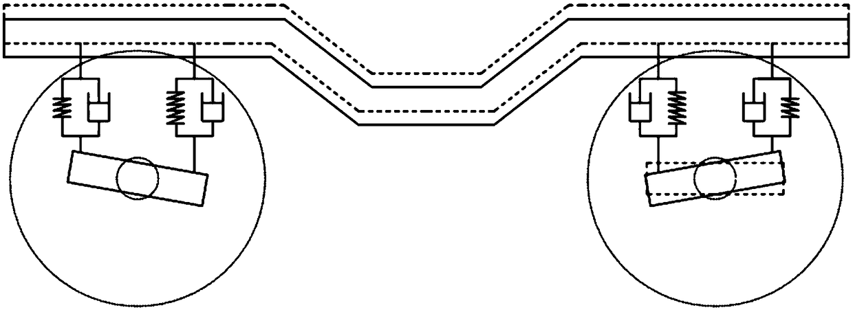
[0013] refer to figure 2 , image 3 , the whole device is mainly composed of the main structure of the steel spring structure 2 and the rubber spring structure 3 in parallel to carry the vertical load. At the same time, the two springs have different vertical stiffness and damping. Under the action of the vertical load, they have different expansion and contraction. The vertical compression rate of the spring structure 3 is smaller than the expansion and contraction of the steel spring structure 2, so the axle box is twisted...


PUM


Abstract

A railway vehicle primary suspension structure is characterized in that a steel spring is used on the outer side of an axle, a rubber spring is used on the inner side of the axle, the steel spring andthe rubber spring are connected through an axle box structure and bears primary suspension and vertical load together, and the rubber spring provides lateral and longitudinal stiffness. The structurecost is lower, and the structure has greater displacement ability under the same load. When the load of a vehicle body changes, the novel primary suspension structure has displacement more than the vertical displacement of the vehicle body and thus can provide more bearing capacity faster to make the vehicle stable, and meanwhile it is ensured that the height of the floor of the vehicle body doesnot change too much. In addition, the steel spring on the outer side has greater deflection. The bogie with said suspension structure can improve the hunting instability critical speed of the vehicleand maximize the operation speeds of existing metro vehicles. At the same time, the structure can also be applied to railway vehicles such as inter-city vehicles with higher speed.

Description

technical field [0001] The invention belongs to the technical field of rail vehicle bogies, in particular to a primary suspension system. Background technique [0002] The existing vehicle primary suspension systems mainly include fixed positioning, guide frame positioning, dry friction guide column positioning, oil guide cylinder positioning, pull plate positioning, pull rod positioning, pivoting arm positioning, and rubber spring positioning. At present, domestic trunk line railways and EMU bogies generally adopt steel spring primary suspension and rubber node positioning structure. The other is a commonly used structure for subway vehicles, using conical rubber springs to provide vehicle primary suspension and longitudinal positioning. [0003] Steel springs can have better load-bearing capacity in the vertical direction, but the transmission capacity of longitudinal force is weak; the application of rubber springs to low-speed vehicles can provide stable vibration reduct...

Claims


Application Information

Patent Timeline
Patent Type & Authority Applications(China)
IPC IPC(8): B61F5/30
CPCB61F5/301B61F5/305
Inventor 宋春元李晓峰刘闯段亮
Owner CRRC CHANGCHUN RAILWAY VEHICLES CO LTD
Learn More