
Periodic suction type textile fabric dust removal device

A technology of textile cloth and dust cleaning device, which is applied in the field of textile equipment, can solve the problems of secondary pollution of cloth, difficult dust collection in dust removal and exhaust outlets, difficulty in dust removal work to achieve the expected effect, and achieve the effect of avoiding secondary pollution

Active Publication Date: 2019-03-08
浙江越剑机电科技有限公司
View PDF8 Cites 5 Cited by
  • Summary
  • Abstract
  • Description
  • Claims
  • Application Information

AI Technical Summary

Problems solved by technology

[0003] Chinese patent (Application Publication No. CN 108147179A) discloses a cloth rewinding device that can be cleaned and arranged, including a base, and a cloth feeding device and a cloth rewinding roller are respectively installed on the opposite ends of the top of the base. The feeding device includes an upper feed roller and a lower feed roller installed at the bottom of the upper feed roller. By hitting and cleaning the surface of the cloth that eliminates the electrostatic attraction, the cleanness of the cloth winding is further improved, and the quality of the cloth winding is improved. It is difficult to effectively collect dust at the dust removal outlet, and the dust circulation in the dust protection cover will cause secondary pollution to the fabric, and the dust removal work is difficult to achieve the expected effect

Method used


Image

  • Periodic suction type textile fabric dust removal device
  • Periodic suction type textile fabric dust removal device
  • Periodic suction type textile fabric dust removal device

Examples


Embodiment Construction

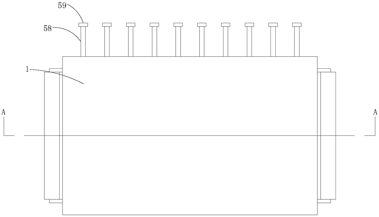
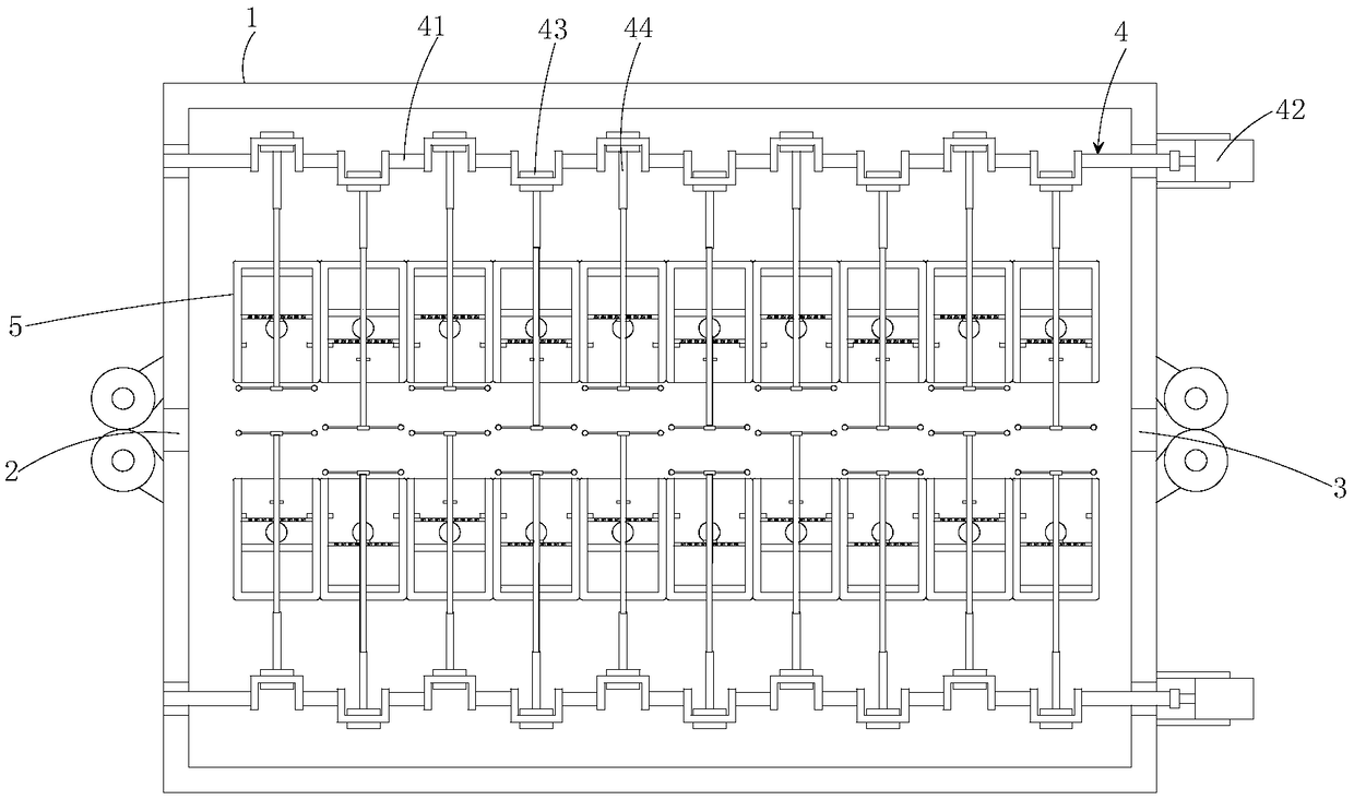
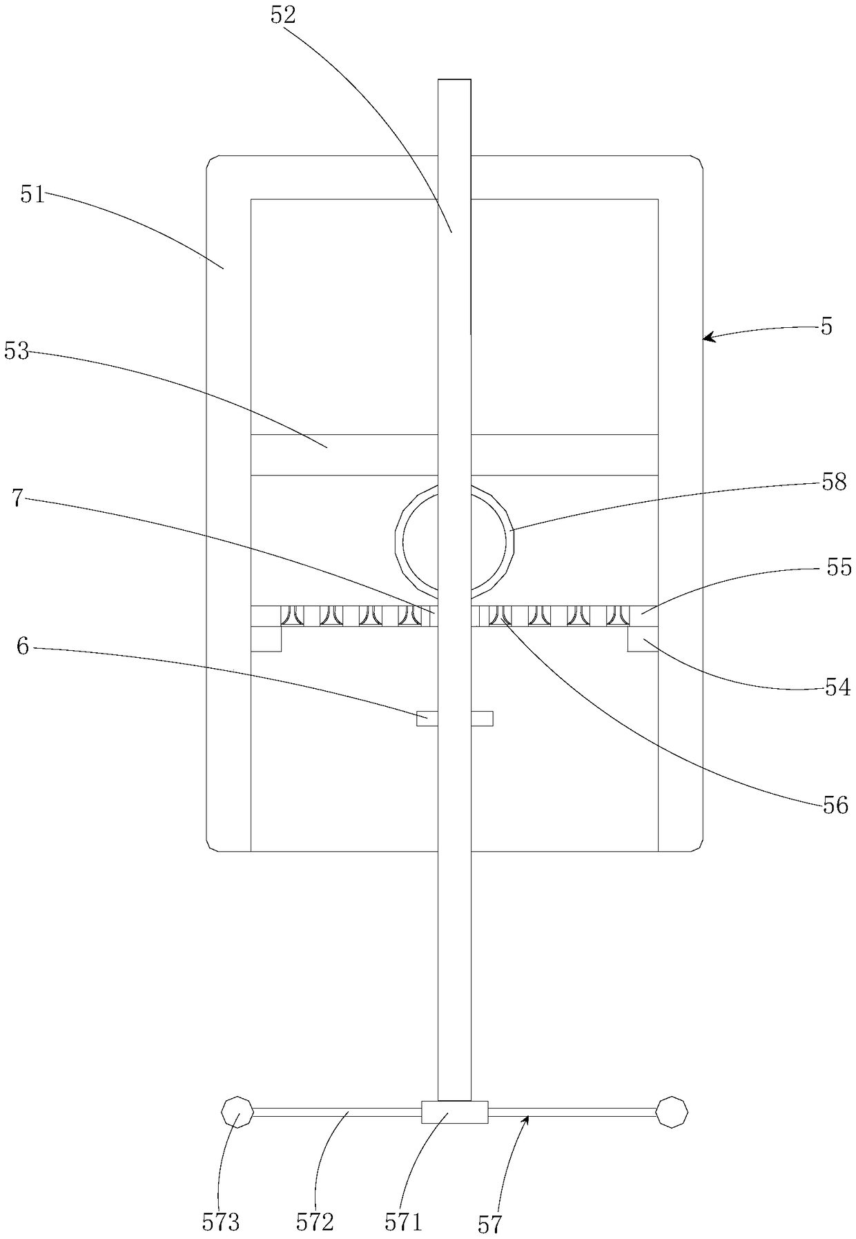
[0028] see Figure 1-3 , the present invention provides a technical solution: a periodic suction type textile cloth dust cleaning device, including a box body 1, a strip-shaped feed port 2, a strip-shaped discharge port 3, two transmission mechanisms 4 and two dust collectors Mechanism 5, the strip-shaped feeding port 2 and the strip-shaped discharging port 3 are set on the left and right side walls of the box body 1 respectively and are symmetrical to each other. Two transmission mechanisms 4 are set at the upper and lower ends of the box body 1. The mechanism 5 is set inside the box body 1 and is located between the two transmission mechanisms 4, and the two dust removal mechanisms 5 and the two transmission mechanisms 4 are all based on the connection line between the strip-shaped feed port 2 and the strip-shaped discharge port 3 symmetry.

[0029] The transmission mechanism 4 includes a crankshaft 41, a drive motor 42, a collar 43 and a transmission rod 44. The two ends o...


PUM


Abstract

The invention belongs to the technical field of textile instruments and discloses a periodic suction type textile fabric dust removal device. The periodic suction type textile fabric dust removal device comprises a box body, a strip-shaped feeding port, a strip-shaped discharging port, two transmission mechanisms and two dust removal mechanisms; the strip-shaped feeding port and the strip-shaped discharging port are symmetrically formed in the left and right side walls of the box body respectively, the two transmission mechanisms are disposed at the upper and lower ends of the interior of thebox body respectively, and the two dust removal mechanisms are disposed in the box body and located between the two transmission mechanisms. According to the periodic suction type textile fabric dustremoval device, through arrangement of the dust removal mechanisms, both sides of a fabric are beaten synchronously to remove dust, and meanwhile the periodicity formed by the rotation of crankshaftscan be adopted for making dust obtained by beating of each beating mechanism below a single air cylinder recycled by an adjacent air cylinder, so that a dust recovery process is more targeted. At thesame time, the dust can be uniformly discharged during the cycle operation. After the dust is beaten out, the circulation of the dust cannot occur in the box body, and secondary contamination of the fabric is avoided.

Description

technical field [0001] The invention relates to the technical field of textile equipment, in particular to a periodic suction type textile cloth dust cleaning device. Background technique [0002] After the textile fabric is produced, a lot of dust is often attached to its surface. On the one hand, it is produced in the raw material yarn or after the dye is dried. On the other hand, it is the accumulation of dust floating in the air in the production workshop. The cloth is cleaned of dust. [0003] Chinese patent (Application Publication No. CN 108147179A) discloses a cloth rewinding device that can be cleaned and arranged, including a base, and a cloth feeding device and a cloth rewinding roller are respectively installed on the opposite ends of the top of the base. The feeding device includes an upper feed roller and a lower feed roller installed at the bottom of the upper feed roller. By hitting and cleaning the surface of the cloth that eliminates the electrostatic attr...

Claims


Application Information

Patent Timeline
IPC IPC(8): D06G1/00
CPCD06G1/00
Inventor 李兵
Owner 浙江越剑机电科技有限公司
Learn More