Finalized prefabricated type reinforced concrete support cover plate and construction method
A reinforced concrete, prefabricated assembly technology, applied in excavation, infrastructure engineering, construction, etc., can solve problems such as unfavorable safe and civilized construction, time-consuming and laborious, and achieve the effect of being conducive to safe and civilized construction control, reducing operation time, and easy construction.
- Summary
- Abstract
- Description
- Claims
- Application Information
AI Technical Summary
Problems solved by technology
Method used
Image

Examples
Embodiment 1
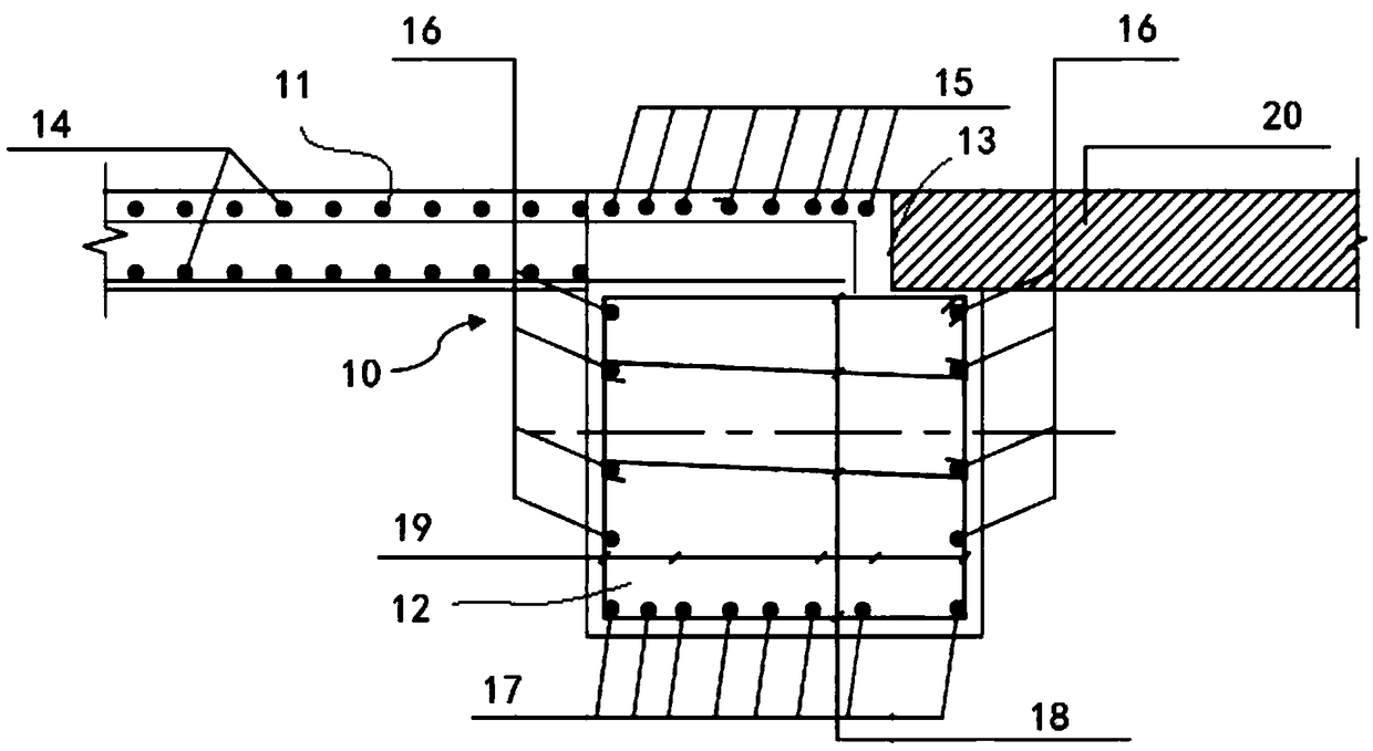
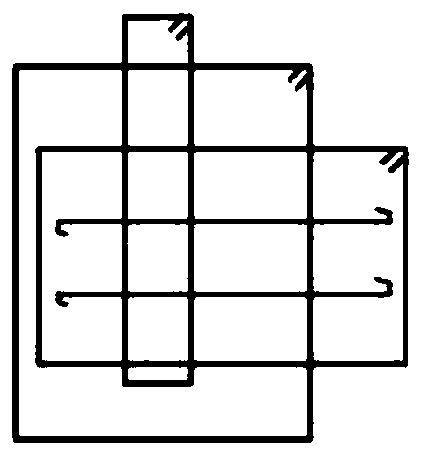
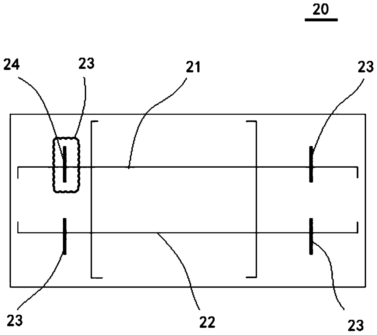
[0032] Such as figure 1 shown, see also Figure 2 to Figure 5 , the finalized prefabricated reinforced concrete support cover plate 20 provided in this embodiment is used for installation at the collision point between the support trestle bridge 10 and the collision member in the cast-in-place reinforced concrete support structure, and the support trestle bridge 10 is at the collision position The L-shaped groove 13 is made, and the cover plate 20 is prefabricated in advance, and is configured to hoist the cover plate 20 to the L-shaped groove 13 after the maintenance of the supporting trestle 10 is completed.
[0033] Such as figure 1 As shown, in this embodiment, the support trestle 10 includes a beam body 11, the support trestle 10 is provided with a support 12 at the collision point, and the support 12 is made at the outer side of the support trestle 10 The L-shaped groove 13.
[0034] Such as figure 1 As shown, in this embodiment, the height of the support 12 is 650 m...
Embodiment 2
[0046] The construction method of the finalized prefabricated reinforced concrete support cover plate in the first embodiment is carried out according to the following steps,
[0047] prefabricated cover;
[0048] On-site pouring of supporting trestle bridges and making L-shaped grooves;
[0049] After the maintenance of the supporting trestle is completed, the cover plate is hoisted to the L-shaped groove.
PUM
| Property | Measurement | Unit |
|---|---|---|
| Height | aaaaa | aaaaa |
| Width | aaaaa | aaaaa |
| Height | aaaaa | aaaaa |
Abstract
Description
Claims
Application Information
PatSnap Eureka turns technology decisions into work you can execute. Powered by our Innovation Knowledge Graph, it runs expert workflows across engineering, life sciences, materials and intellectual property. Get your review-ready output in minutes.


