
Fuel supply system and supply method for high-speed air-breathing engine

A technology of fuel supply system and engine, which is applied in ramjet engines, turbine/propellant fuel delivery systems, charging systems, etc., can solve the problems of low chemical heat sink and weak selectivity, and achieve high density specific impulse, Good combustion characteristics, effect of reducing demand

Active Publication Date: 2019-03-08
XIAN AEROSPACE PROPULSION INST
View PDF4 Cites 7 Cited by
  • Summary
  • Abstract
  • Description
  • Claims
  • Application Information

AI Technical Summary

Problems solved by technology

[0004] In order to overcome the technical problems of low selectivity and low chemical heat sink in the existing engine fuel cracking process, the present invention provides a fuel supply system and supply method for high-speed air-breathing engines

Method used


Image

  • Fuel supply system and supply method for high-speed air-breathing engine
  • Fuel supply system and supply method for high-speed air-breathing engine

Examples


Embodiment Construction

[0031] The present invention will be described in detail below in conjunction with the accompanying drawings.

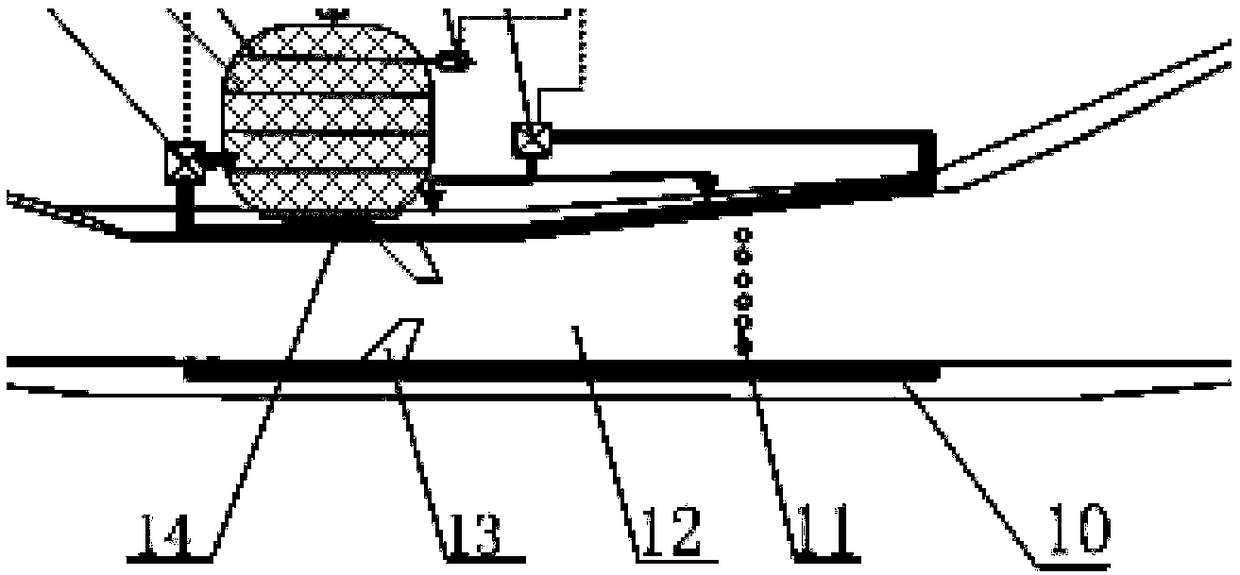
[0032] figure 1 The schematic diagram of the hypersonic air-breathing engine for applying the fuel supply system of the high-speed air-breathing engine of the present invention, the air flow path of the engine includes the air intake system 15, the combustion chamber 12 and the nozzle 9 arranged in sequence, and the engine wall is provided with Heat exchange channel 10. What intake system 15 enters is air.

[0033] Such as figure 2 As shown, the fuel supply system of the present invention includes a fuel storage tank 2, an electric heating device 3, a delivery pipeline, a distribution pipeline, a plurality of injectors 11, a gas cylinder 5, a pressure reducing valve 6 and a control unit 8; The storage tank 2 is arranged on the heat exchange surface 14 of the heat exchange channel 10 of the high-speed air-breathing engine, and solid fuel is stored in the fuel stor...


PUM


Abstract

The invention relates to a fuel supply system and supply method for a high-speed air-breathing engine. The fuel supply system and supply method aim to overcome the technical problems of poor selectivity and low chemical heat sink in the fuel cracking process of an existing engine. The supply system comprises a fuel storage tank, an electric heating device, a conveying pipeline, a distribution pipeline, a plurality of injectors, a gas cylinder, a pressure reducing valve and a control unit. The fuel storage tank is arranged at the heat exchange face of a heat exchange channel of the high-speed air-breathing engine, and solid fuel is stored in the fuel storage tank. An outlet of the gas cylinder is connected with the fuel storage tank through the pressure reducing valve. The electric heatingdevice is used for heating the fuel storage tank. Outlets of the injectors face the interior of a combustion chamber. An inlet of the conveying pipeline is connected with an outlet of the fuel storagetank, an outlet of the conveying pipeline is connected with an inlet of the heat exchange channel, and an electromagnetic valve is arranged on the conveying pipeline. The distribution pipeline comprises a main pipeline body, a plurality of branch pipeline bodies and a fuel distribution valve, wherein an inlet of the main pipeline is connected with an outlet of the heat exchange channel.

Description

technical field [0001] The invention belongs to the field of rocket ramjet combined engines, and in particular relates to a fuel supply system and a supply method of a high-speed air-breathing engine. Background technique [0002] Hypersonic air-breathing engines such as scramjet engines and RBCC engines work under hypersonic flow conditions, and combustion organization and thermal protection are their core key technologies. The Mach number of the airflow in the combustion chamber 12 of the engine is relatively large, and the combustion organization is difficult. It is necessary to realize the efficient heat release of the fuel within the limited length of the combustion chamber 12, which requires that the fuel entering the combustion chamber 12 should have a short ignition delay time and a flame propagation velocity. Fast, low self-ignition characteristics. In addition, hypersonic air-breathing engines are subjected to a very harsh thermal environment, and active fuel cool...

Claims


Application Information

Patent Timeline
IPC IPC(8): F02C7/22F02C7/224F02K7/18
CPCF02C7/22F02C7/224F02K7/18
Inventor 杜泉付秀文李光熙刘昊张蒙正路媛媛汪广旭
Owner XIAN AEROSPACE PROPULSION INST
Learn More