Truss type supporting structure of space wide camera

A support structure, truss-type technology, applied in the connection of rods, connecting members, supporting machines, etc., can solve the problems of difficult to meet the support structure, and achieve the effect of overcoming low stiffness and thermal stability and realizing a large field of view.

Inactive Publication Date: 2019-03-08
ACAD OF OPTO ELECTRONICS CHINESE ACAD OF SCI
View PDF5 Cites 6 Cited by
  • Summary
  • Abstract
  • Description
  • Claims
  • Application Information

AI Technical Summary

Problems solved by technology

[0004] Support structures in the prior art are difficult to meet the above requirements

Method used


Image

  • Truss type supporting structure of space wide camera
  • Truss type supporting structure of space wide camera
  • Truss type supporting structure of space wide camera

Examples


specific Embodiment approach

[0014] The truss type support structure of the space wide camera of the present invention, its preferred specific embodiment is:

[0015] It includes a camera frame, a truss assembly and a fixed frame, the camera frame is connected to the fixed frame through the truss assembly, the fixed frame is provided with threaded holes fixedly connected with the satellite platform, the truss assembly includes a truss rod, and the truss rod The upper end and the lower end are respectively provided with an upper joint and a lower joint.

[0016] The camera frame is provided with assembly shaft holes for four cameras, one side of the camera frame is provided with a flange mounting surface and threaded holes, the four cameras are mounted on the flange mounting surface by screws, and the other side of the camera frame is provided with a truss assembly The mounting threaded hole for connecting the upper joint;

[0017] The fixed frame is provided with an installation threaded hole connected w...

specific Embodiment

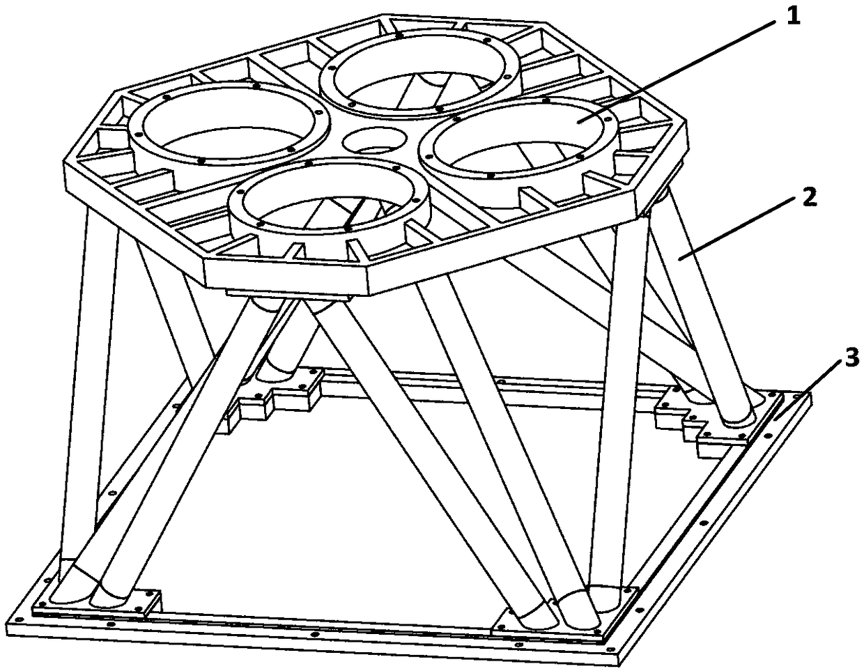
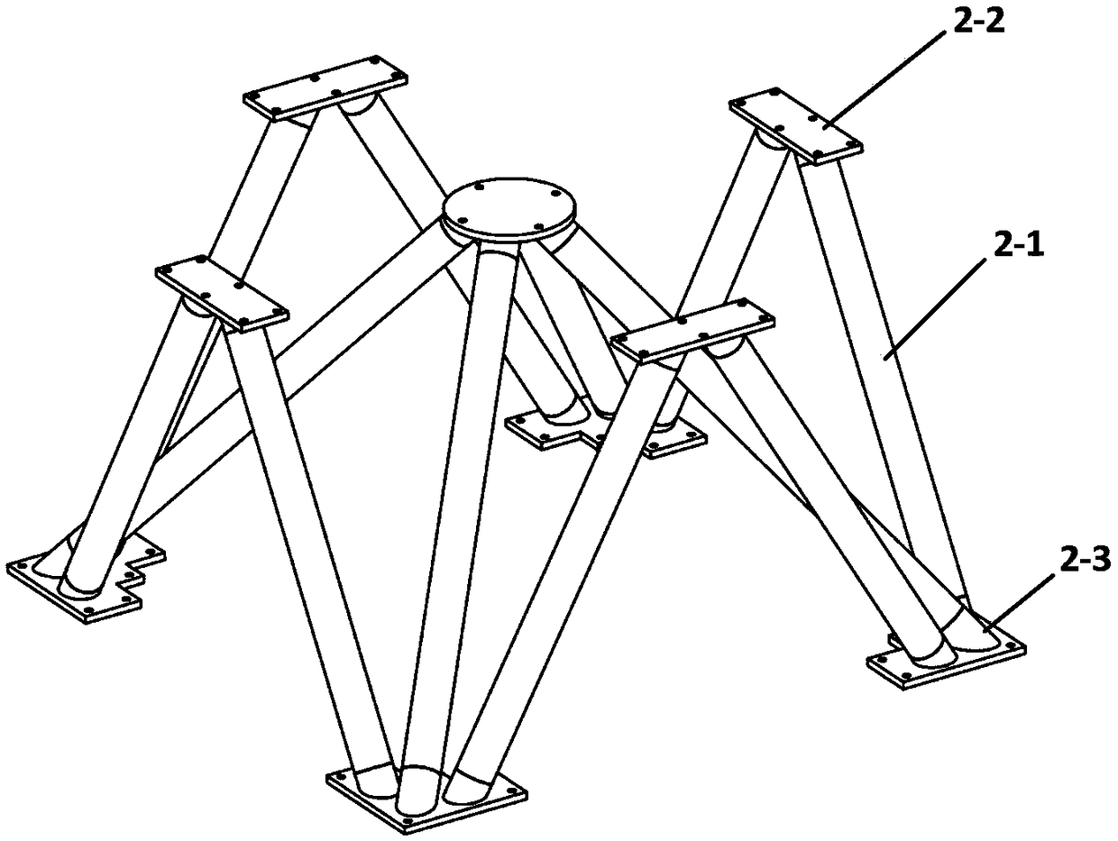
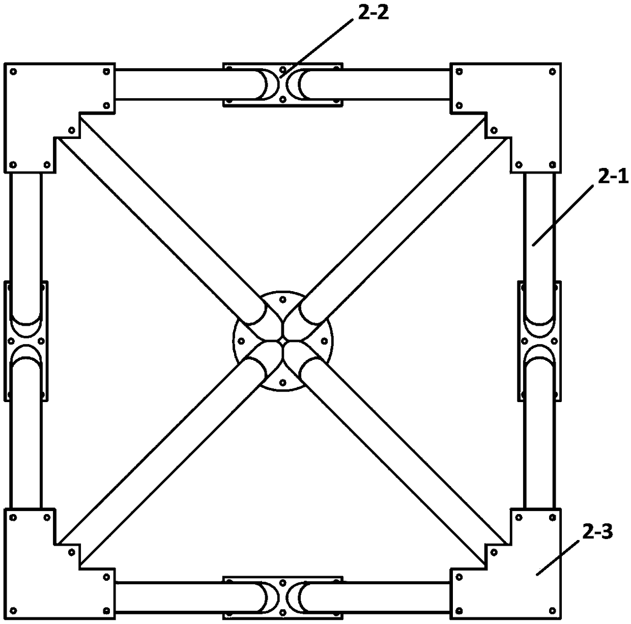
[0024] Such as Figure 1 to Figure 4 As shown, it includes a camera frame 1, a truss assembly 2 and a fixed frame 3. The camera frame 1 is connected to the fixed frame 3 through the truss assembly 2, and the fixed frame 3 can be fixedly connected to the satellite platform through threaded holes. Wherein, the truss assembly 2 is composed of a truss rod 2-1, an upper joint 2-2 and a lower joint 2-3.

[0025] The camera frame 1 is provided with mounting shaft holes for four cameras, and the angle of the axis of the shaft holes can be determined according to the deflection angle of the optical cameras. One side of the camera frame 1 is provided with a flange mounting surface and threaded holes. Four cameras can be mounted on the flange mounting surface by screws, and the positional accuracy can be ensured. If necessary, pins can be used at the connection position to ensure the relative positional relationship between the cameras. The other side of the camera frame 1 is provided w...


PUM


Abstract

The invention discloses a truss type supporting structure of a space wide camera. The truss type supporting structure comprises a camera frame, a truss assembly and a fixed frame, wherein the camera frame is connected with the fixed frame through the truss assembly; the fixed frame is provided with a threaded hole fixedly connected with a satellite platform; the truss assembly comprises 12 truss rods, 5 upper connectors and 4 lower connectors; the 5 upper connectors are 4 circumferentially uniformly distributed two-way connectors and 1 four-way connector arranged at the circumferential center;the 4 lower connectors are 4 circumferentially uniformly distributed three-way connectors; the four-way connector is connected with the 4 three-way connectors through the truss rods; the two-way connectors are connected with the two adjacent three-way connectors through the truss rods; the 12 truss rods are manufactured from a carbon fiber composite; and the upper connectors and the lower connectors are manufactured from a titanium alloy material. According to the truss type supporting structure, 4 high-resolution optical cameras can be mounted according to a certain angle, the large-mass cameras can be effectively supported, the detect that rigidity and heat stability of a conventional space camera supporting structure are relatively low is overcome, and optical imaging requirements of large-view field large-ground width space cameras are achieved.

Description

technical field [0001] The invention relates to a space remote sensing device, in particular to a truss type support structure of a space wide camera. Background technique [0002] As the main equipment for space observation of the earth, space cameras not only require high spatial resolution, but also require the satellite revisit cycle to be shorter and shorter, so as to obtain as much ground information as possible. However, due to the orbital height of the satellite itself and the high cost, it is often unrealistic for commercial spaceflight to realize the networking of multiple high-resolution satellites to shorten the revisit cycle, so the high-resolution, large-width space camera has become the only Solution. [0003] The support structure of the space camera is the main component of the space camera. It needs to provide reliable support and installation interfaces for each optical component, and at the same time resist the influence of the space environment on the o...

Claims


Application Information

Patent Timeline
Patent Type & Authority Applications(China)
IPC IPC(8): F16M5/00F16B7/08
CPCF16B7/00F16M5/00
Inventor 张丹丹相里斌吕群波刘扬阳赵娜李伟艳王建威方煜
Owner ACAD OF OPTO ELECTRONICS CHINESE ACAD OF SCI
Why Eureka
Try Eureka