Check patentability & draft patents in minutes with Patsnap Eureka AI!

Intelligent defoaming device

A defoaming device and intelligent technology, applied in the pipeline system, mechanical equipment, gas/liquid distribution and storage, etc., can solve the problems of increasing the labor intensity of workers, affecting the effect of gas-liquid separation, and the failure of defoaming agent to be injected smoothly, etc., to achieve The effect of high production efficiency and simple structure

Pending Publication Date: 2019-03-08
成都孚吉科技有限责任公司
View PDF0 Cites 0 Cited by
  • Summary
  • Abstract
  • Description
  • Claims
  • Application Information

AI Technical Summary

Problems solved by technology

However, in the continuous production process, in the event of unexpected situations such as power failure or defoamer filling equipment failure, the defoamer cannot be injected into the pipeline smoothly, affecting the gas-liquid separation effect
In addition, the liquid defoamer injected into the main pipeline is made by mixing and diluting the stock solution of the defoamer and water. In the prior art, this dilution process is usually done manually, which also increases the labor intensity of the workers.

Method used


Image

  • Intelligent defoaming device
  • Intelligent defoaming device
  • Intelligent defoaming device

Examples


Embodiment Construction

[0022] The technical solution of the present invention will be further described in detail below in conjunction with the accompanying drawings, but the protection scope of the present invention is not limited to the following description.

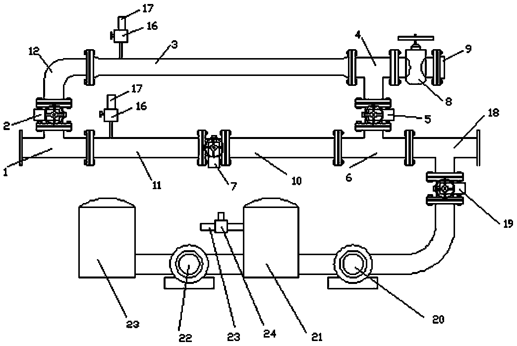
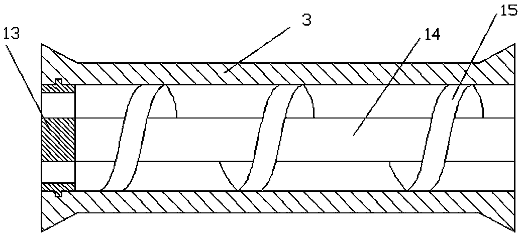
[0023] Such as figure 1 As shown, an intelligent defoaming device includes an outlet tee 1, an outlet valve 2, a connecting pipe c12, a substrate main pipe 3, a packing tee 4, an electric inlet valve 5 and an inlet tee 6 connected in sequence. A solid defoaming agent is arranged in the main pipe 3 of the base body, a filling valve 8 is connected to one end of the packing tee 4 away from the main pipe 3 of the base body and the electric inlet valve 5 , and a cover valve 9 is connected to the other end of the filling valve 8 . An electric switching valve 7, a connecting pipe a10 and a connecting pipe b11 are also provided, and the two ends of the electric switching valve 7 are respectively connected to the inlet tee 6 and the outlet tee 1 thr...


PUM


Abstract

The invention discloses an intelligent defoaming device, and relates to the field of petroleum and natural gas pipeline accessory ingredient filling devices. The intelligent defoaming device comprisesan outlet tee joint, an outlet valve, a connecting pipe c, a body main pipe, a filling tee joint, an electric inlet valve, an inlet tee joint, an electric changeover valve, a connecting pipe a, a connecting pipe b and a controller. The outlet tee joint, the outlet valve, the connecting pipe c, the body main pipe, the filling tee joint, the electric inlet valve and the inlet tee joint are connected sequentially; solid defoaming agents are arranged in the body main pipe; the end, away from the body main pipe and the electric inlet valve, of the filling tee joint is connected with a filling valve, and the other end of the filling valve is connected with a cover plate valve; the two ends of the electric changeover valve are correspondingly connected with the inlet tee joint and the outlet teejoint through the connecting pipe a and the connecting pipe b; and the controller is in electric connection with the outlet valve, the electric inlet valve and the electric changeover valve correspondingly. According to the intelligent defoaming device, the structure is simple, the production efficiency is high, the situation that production interruption caused by sudden factors such as power cutinfluences on the production is avoided, at the same time, the filling forms and dosage of the defoaming agents can be intelligently controlled, and the labour intensity of workers is reduced.

Description

technical field [0001] The invention relates to the field of oil and gas production equipment, in particular to an intelligent defoaming device. Background technique [0002] In the exploitation of oil and natural gas, with the prolongation of production time, the gas well enters the middle and later stages, its pressure and production capacity drop rapidly, the liquid carrying capacity of the gas well becomes worse, and there are different degrees of liquid accumulation in the wellbore. In order to discharge wellbore fluid and increase gas well production, foam drainage technology is usually used. However, large-scale foam drainage will affect the normal operation of station equipment, increase pipe network friction and pigging difficulty, and affect production results. To solve this problem, in the prior art, a high-pressure plunger pump is usually used to deliver a defoamer into the pipeline to eliminate air bubbles in the pipeline. However, in the continuous production ...

Claims


Application Information

Patent Timeline
Patent Type & Authority Applications(China)
IPC IPC(8): F17D3/12
CPCF17D3/12
Inventor 李相云戚杰谷显胡
Owner 成都孚吉科技有限责任公司
Features
  • R&D
  • Intellectual Property
  • Life Sciences
  • Materials
  • Tech Scout
  • Unparalleled Data Quality
  • Higher Quality Content
  • 60% Fewer Hallucinations
Learn More