Remote solar steam generator

A technology of solar steam and generator, which is applied in the steam generation method using solar energy, steam generation, solar thermal power generation, etc. It can solve the problems of low intelligence, troublesome remote monitoring, and low output efficiency, and achieve high thermal efficiency. Transmission speed, avoiding uneven heating, and achieving the effect of pressure equalization

Active Publication Date: 2019-03-08
HENAN JIUYE CHEM EQUIP
View PDF5 Cites 0 Cited by
  • Summary
  • Abstract
  • Description
  • Claims
  • Application Information

AI Technical Summary

Problems solved by technology

The current steam generator is also widely used in the treatment of various diseases, especially in the treatment of chronic diseases caused by aging and old damage to muscles and ligaments, such as CN2167709Y patent, but in the current prior art, such as CN2167709Y Patent, because the steam is generated directly by heating, the temperature of the generated steam will be too high, and it will cause too much moisture in the generated steam, and the drug may be deposited in the lower part because it is a particle, so the ejected steam is effective The content of ingredients is too low, and the temperature is too high, and the degree of intelligence in the existing technology is not high, and effective intelligent operation cannot be carried out
[0005] In the background technology, when the steam generator is heated by solar energy, the solar energy either directly heats the steam drum, or generates steam through secondary heat exchange, especially directly heats the steam drum, and utilizes the convective heat exchange inside the steam drum to heat the upper and lower parts of the steam drum. The convective heat exchange of the fluid, but in this case, the lower part of the hot fluid needs to be naturally convected to the upper part, and the heat transfer efficiency is low
[0006] The existing solar steam generators have low output efficiency and low intelligence, and it is troublesome to realize remote monitoring. Therefore, it is necessary to design a solar steam generator based on intelligent control

Method used


Image

  • Remote solar steam generator
  • Remote solar steam generator
  • Remote solar steam generator

Examples


Embodiment 1

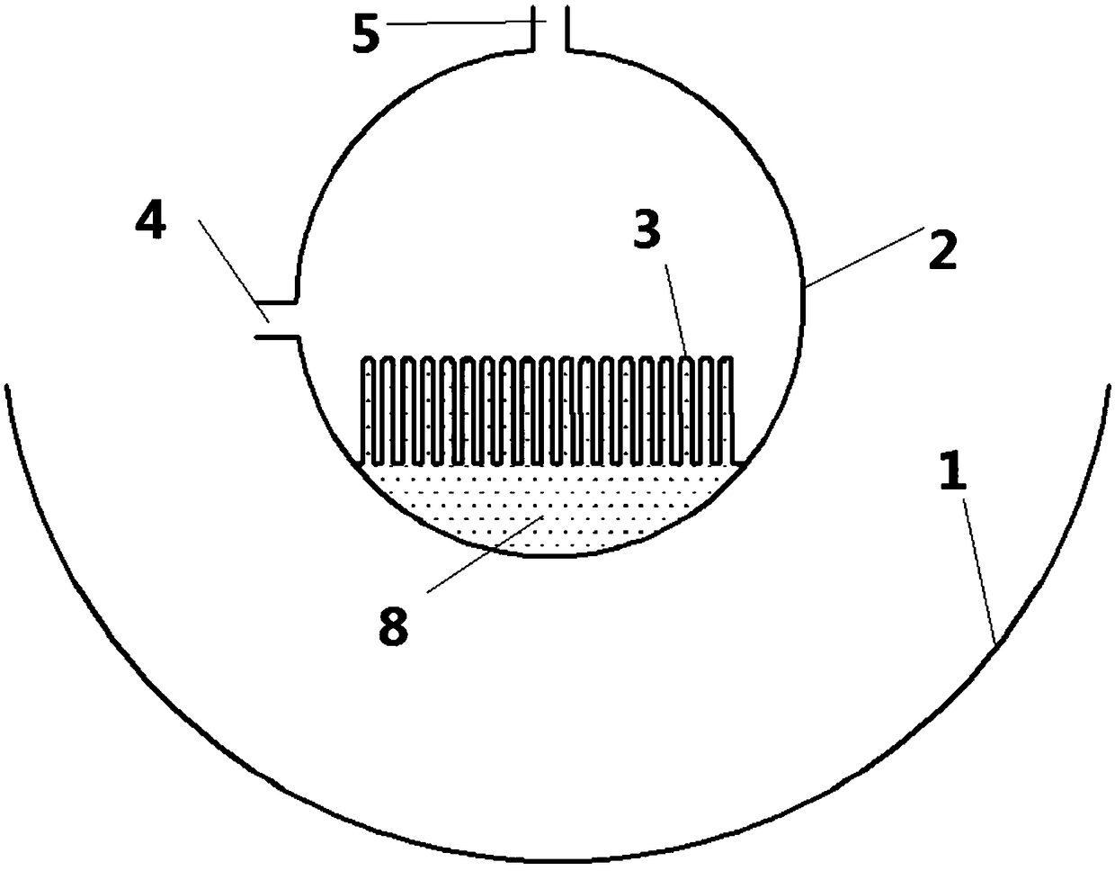
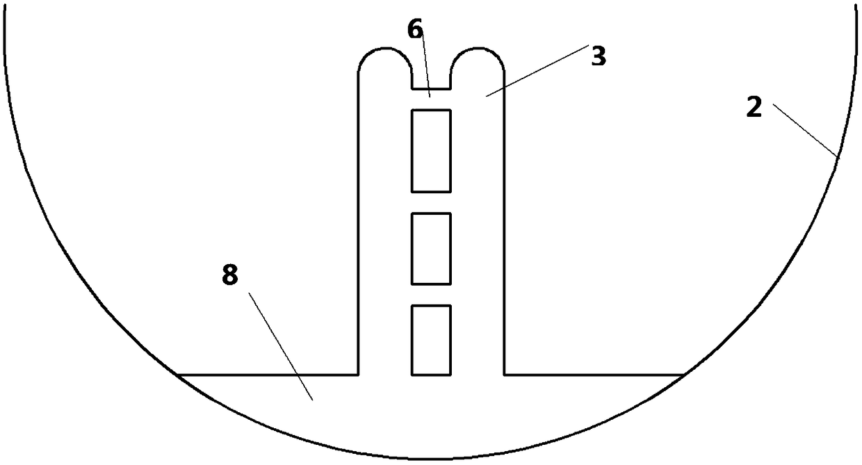
[0163] As an improvement, a temperature sensor is arranged in the steam drum 3 for measuring the temperature of the steam in the steam drum 3 . The water inlet pipe 4 and the steam outlet 5 of the steam drum 3 are respectively provided with a water inlet valve and a steam valve, and the temperature sensor, the water inlet valve and the steam valve are connected with the central controller 7 for data. The controller 7 is connected to the cloud server 10, and the cloud server 10 is connected to the client 9, wherein the controller 7 transmits the data of the measured temperature sensor, water inlet valve and steam valve to the cloud server 10, and then transmits the data to the cloud server 10 through the cloud server 10. Client 9, the client 9 is a mobile phone, the mobile phone is installed with an APP program, the user can select the working mode of automatic control or manual control on the client 9, and the controller 7 controls the working mode selected by the customer to c...

Embodiment 2

[0173] As an improvement, the central controller 7 ensures that the outlet steam temperature in the steam drum reaches a constant value by controlling the opening of the water inlet valve and the steam valve. That is, the temperature of the steam at the steam outlet of the steam drum 3 is adjusted by adjusting the said flow rate entering the steam drum 3 and leaving the steam drum 3 .

[0174] An outlet pipe temperature sensor is arranged on the steam outlet 5 of the steam drum, and the outlet temperature sensor is connected with the data of the central controller 7, and the outlet pipe temperature sensor, the water inlet valve and the steam valve are connected with the data of the central controller 7. The controller 7 is connected to the cloud server 10, and the cloud server 10 is connected to the client 9, wherein the controller 7 transmits the data of the measured temperature sensor, water inlet valve and steam valve to the cloud server 10, and then transmits the data to th...

Embodiment 3

[0185] As a further improvement of the second embodiment, the opening and closing of the steam valve and the water inlet pipe valve are controlled by measuring the temperature of the water in the steam drum 3 .

[0186] The controller 7 is connected to the cloud server 10, and the cloud server 10 is connected to the client 9, wherein the controller 7 transmits the data of the measured temperature sensor, water inlet valve and steam valve to the cloud server 10, and then transmits the data to the cloud server 10 through the cloud server 10. Client 9, the client 9 is a mobile phone, the mobile phone is installed with an APP program, the user can select the working mode of automatic control or manual control on the client 9, and the controller 7 controls the working mode selected by the customer to control the water inlet valve and steam valve opening.

[0187] By setting the manual or automatic control mode, a multi-method control method can be provided for the user, which impro...


PUM


Abstract

The invention provides a remote solar steam generator, which comprises a reflector and a steam pocket. The steam pocket is located at the focus of the reflector and internally provided with a temperature sensor to measure the temperature of steam in the steam pocket; a water feeding valve and a steam valve are arranged at a water feeding pipe and a steam outlet of the steam pocket correspondingly;the temperature sensor, the water feeding valve and the steam valve are in data connection with a central controller; and the controller is connected with a cloud server, the cloud server is connected with a client side, measured data of the temperature sensor, the water feeding valve and the steam valve are transmitted to the cloud server by the controller and then transmitted to the client sidethrough the cloud server, and the controller controls the opening degree of the water feeding valve and the steam valve according to the working mode selected by a client. The opening degree of the valves is remotely and intelligently controlled through the temperature of the steam, and thus remote intelligent control of a system is achieved.

Description

technical field [0001] The invention relates to a steam generator technology, in particular to a steam generator of a heat pipe with a new structure. Background technique [0002] Heat pipe technology was developed in Los Alamos, USA in 1963. national laboratory A heat transfer method called a "heat pipe" invented by George Grover element , it makes full use of the principle of heat conduction and the rapid heat transfer properties of phase change media, and quickly transfers the heat of the heating object to the heat source through the heat pipe, and its thermal conductivity exceeds that of any known metal. [0003] Heat pipe technology was widely used in aerospace, military and other industries before. Since it was introduced into the radiator manufacturing industry, people have changed the traditional radiator design ideas and got rid of the single heat dissipation mode that only relies on high air volume motors to obtain better heat dissipation. The use of heat pipe t...

Claims


Application Information

Patent Timeline
Patent Type & Authority Applications(China)
IPC IPC(8): F22B1/00F22B35/00F24S10/95F24S20/40F24S23/72F24S50/40A61J3/00
CPCA61J3/00F22B1/006F22B35/00Y02E10/44
Inventor 不公告发明人
Owner HENAN JIUYE CHEM EQUIP
Why Eureka
Try Eureka