A solid-liquid separation device for photocatalytic treatment of volatile organic pollutants

A volatile organic and solid-liquid separation technology, applied in the field of photocatalytic treatment, can solve the problems of single filtration concentration of volatile organic pollutants and limited overall performance, and achieve the effects of increasing service life, easy adjustment, and increasing sealing performance

Active Publication Date: 2021-10-15
FOSHAN UNIVERSITY
View PDF27 Cites 0 Cited by
  • Summary
  • Abstract
  • Description
  • Claims
  • Application Information

AI Technical Summary

Problems solved by technology

[0003] A kind of in-situ solidification collection device for volatile and semi-volatile organic pollutants in water disclosed in Chinese utility model patent application publication specification CN206756506U, although the in-situ solidification collection device for volatile and semi-volatile organic pollutants in water can be Quickly adsorb or distribute a certain amount of volatile and semi-volatile organic pollutants in the water environment on the micro-probe in situ, avoiding the loss of volatile and semi-volatile organic pollutants during transportation and storage, And can be stored for a long time, however, the in-situ solidification collection device for volatile and semi-volatile organic pollutants in the water body has the disadvantage of a single filtration concentration of volatile organic pollutants, which makes the overall performance of the device limited

Method used


Image

  • A solid-liquid separation device for photocatalytic treatment of volatile organic pollutants
  • A solid-liquid separation device for photocatalytic treatment of volatile organic pollutants
  • A solid-liquid separation device for photocatalytic treatment of volatile organic pollutants

Examples


Embodiment Construction

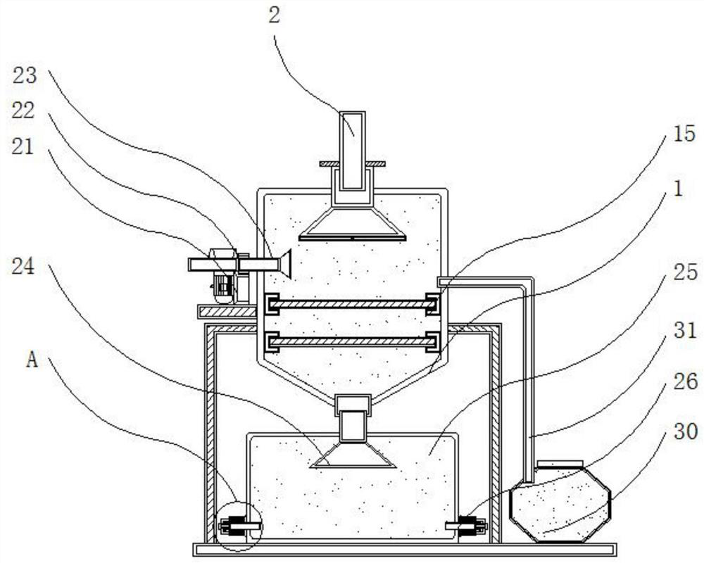
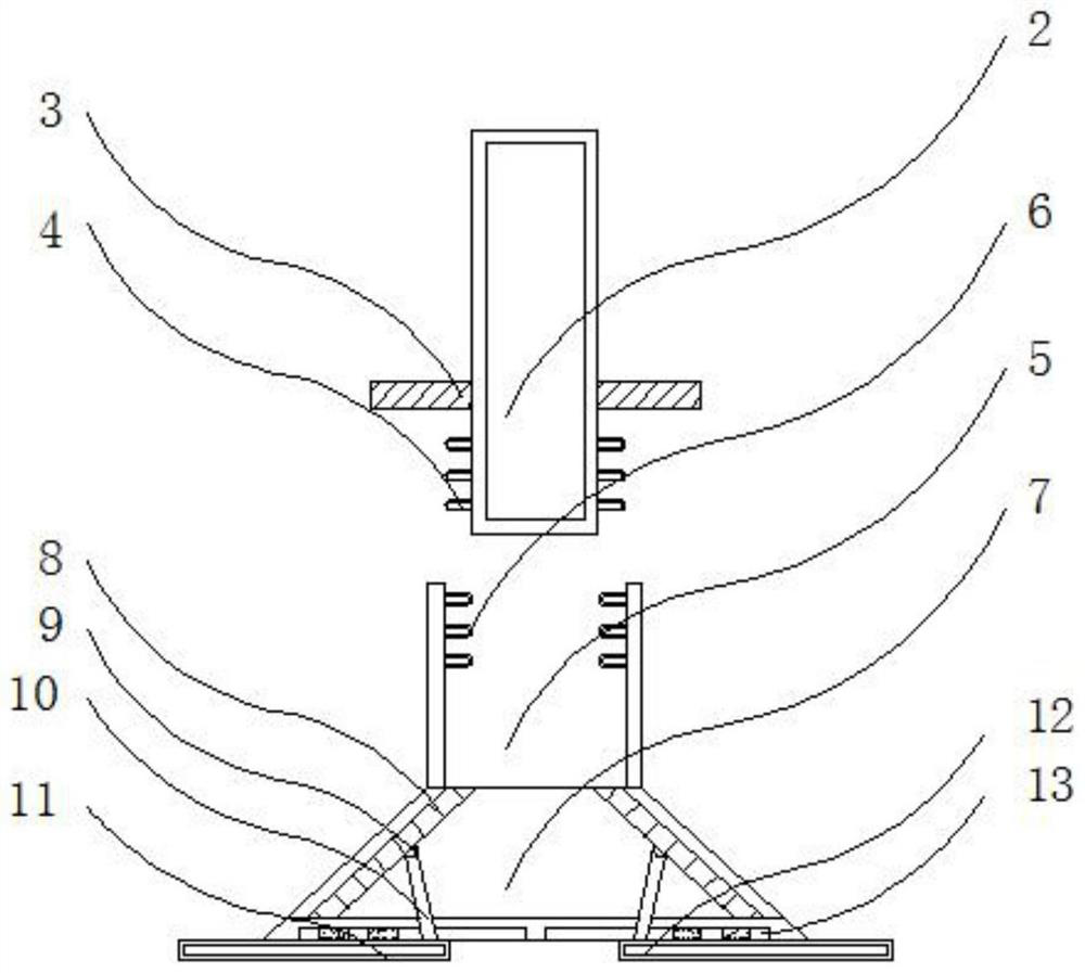
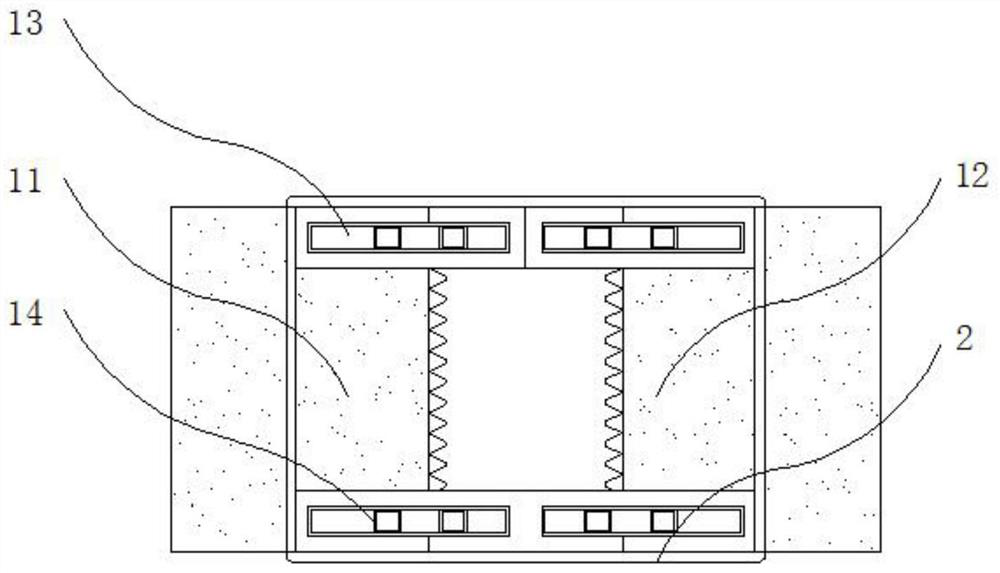
[0028] The following will clearly and completely describe the technical solutions in the embodiments of the present invention with reference to the accompanying drawings in the embodiments of the present invention. Obviously, the described embodiments are only some, not all, embodiments of the present invention.

[0029] In the description of the present invention, unless otherwise stated, the meaning of "plurality" is two or more; the terms "upper", "lower", "left", "right", "inner", "outer" , "front end", "rear end", "head", "tail", etc. indicate the orientation or positional relationship based on the orientation or positional relationship shown in the drawings, and are only for the convenience of describing the present invention and simplifying the description, rather than Nothing indicating or implying that a referenced device or element must have a particular orientation, be constructed, and operate in a particular orientation should therefore not be construed as limiting ...


PUM


Abstract

The invention discloses a solid-liquid separation device for photocatalytic treatment of volatile organic pollutants, relates to the technical field of photocatalytic treatment, and specifically includes a separation chamber, a blower and a gas collection bottle. A material guide pipe is installed above the separation chamber. The blower is installed on the left side of the separation chamber, and the input end and the output end of the blower are respectively flange-connected with an air inlet pipe and an air outlet pipe, and the end of the separation chamber is connected with a discharge pipe, and the end of the discharge pipe A liquid collection box is connected through it, and the gas collection bottle is installed on the right side of the separation chamber, and the top of the gas collection bottle is connected with a gas collection pipe through it. In this photocatalytic solid-liquid separation device for volatile organic pollutants, the end of the feed pipe is embedded in the inside of the feed pipe and is connected to the feed pipe in a flexible manner, which is convenient for users to adjust the gap between the feed pipe and the feed pipe. connection, and inject liquid volatile organic pollutants into the guide tube through external mechanical action or injection.

Description

technical field [0001] The invention relates to the technical field related to photocatalytic treatment, in particular to a solid-liquid separation device for photocatalytic treatment of volatile organic pollutants. Background technique [0002] Photocatalytic treatment is also known as photocatalyst treatment. Photocatalyst is a substance that does not change itself under the irradiation of light, but can promote chemical reactions. Photocatalyst uses the light energy existing in nature to convert it into the energy required for chemical reactions to produce catalysis. , so that the surrounding oxygen and water molecules are excited to become highly oxidative free negative ions, which can not only accelerate the reaction, but also use the definition of nature to avoid waste of resources and the formation of additional pollution. Under photocatalyst treatment, volatile organic Pollutants, the volatile organic pollutants will form solid and liquid states and mix with them. No...

Claims


Application Information

Patent Timeline
Patent Type & Authority Patents(China)
IPC IPC(8): G01N1/34B01D29/01B01D29/56
CPCB01D29/01B01D29/56G01N1/34
Inventor 江学顶许伟城刘俊星
Owner FOSHAN UNIVERSITY
Why Eureka
Try Eureka