
Subway/coal mine backflow track insulation damage position and transition resistance monitoring method

A transition resistance, potential monitoring technology, applied in the direction of grounding resistance measurement, fault location, measurement of resistance/reactance/impedance, etc., to achieve the effect of reasonable cost, simple structure, and easy rapid layout

Active Publication Date: 2019-03-08
CHINA UNIV OF MINING & TECH
View PDF15 Cites 7 Cited by
  • Summary
  • Abstract
  • Description
  • Claims
  • Application Information

AI Technical Summary

Problems solved by technology

Therefore, it is urgent to study the precise positioning method of the ground insulation damage position of the return track under the single-side single-locomotive power supply mode. The location method of track-to-ground insulation damage (Liu Jianhua et al., Urban Rail Transit Research, 2015.09), this method needs to inject a traveling wave signal into the return track where the insulation damage occurs, and the traveling wave signal is reflected back to the signal injection position at the location of the insulation damage. According to The time for the signal to go back and forth between the injection location and the location of the insulation damage and the wave velocity of the traveling wave signal realize the location of the location of the insulation damage. The feasibility and accuracy of this method have only been verified by simulation, and further engineering practice is needed to prove

Method used


Image

  • Subway/coal mine backflow track insulation damage position and transition resistance monitoring method
  • Subway/coal mine backflow track insulation damage position and transition resistance monitoring method
  • Subway/coal mine backflow track insulation damage position and transition resistance monitoring method

Examples


Embodiment Construction

[0020] The technical solutions of the present invention will be further described below in conjunction with the accompanying drawings and embodiments.

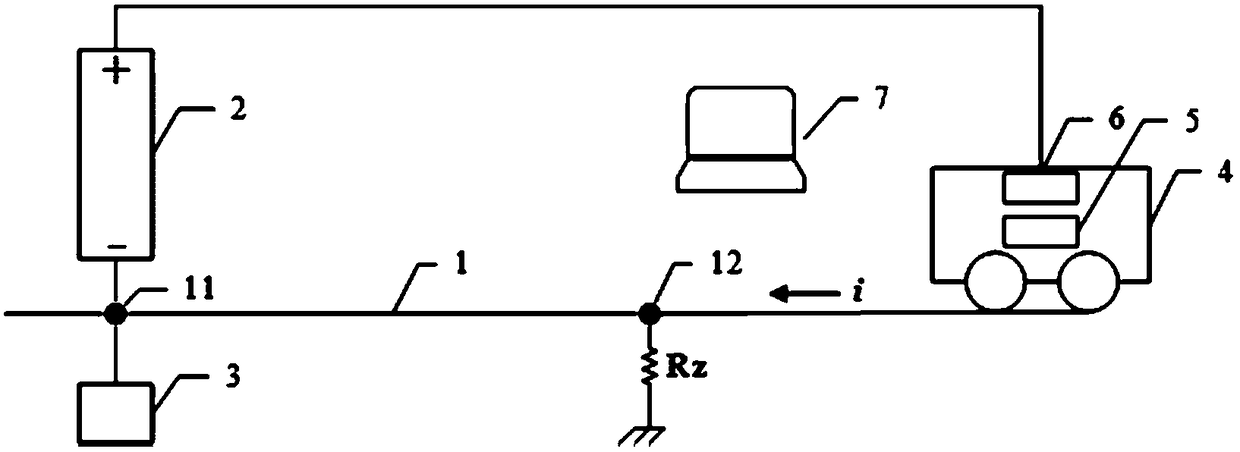
[0021] A kind of subway / coal mine subway / coal mine return track insulation damage position and its transition resistance monitoring method described in the present invention, such as figure 1 shown. Specifically include:

[0022] S1: The return track 1 is connected to the negative pole of the substation 2 through a cable, and the position 11 of the connection point is selected as the reference position.

[0023] S2: install the potential monitoring device 3 at the reference position selected in step S1, and collect the potential data at the reference position at a certain moment; at the same time, install the driving distance monitoring device 5 and the traction current monitoring device 6 on the locomotive 4, and collect the potential data at a certain moment Travel distance data and traction current data of locomotive 4. ...


PUM


Abstract

The invention discloses a subway / coal mine backflow track insulation damage position and transition resistance monitoring method. The method comprises the following steps that a backflow track is connected to the cathode of a power substation, and the position of a connection point is selected as a reference position and a potential monitoring device is installed at the reference position; a running distance monitoring device and a traction current monitoring device are installed on a locomotive, the locomotive moves along the backflow track to the power substation, and the above three monitoring devices send recorded data to a control unit; and the control unit discriminates potential jump and corresponding jump time from received potential data, determines the running distance of the locomotive at the jump time and the total running length of the locomotive so as to determine a ground insulation damage position, and correspondingly acquire the transition resistance value of the ground insulation damage position. In the invention, the ground insulation damage position of the backflow track can be directly and conveniently monitored in on-line and real-time modes, the structure ofa monitoring system is simple, cost is suitable and the method is especially suitable for the application fields of a coal mine or a subway which adopts a direct current traction locomotive and the like.

Description

technical field [0001] The invention belongs to the technical field of track monitoring, and in particular relates to a method for monitoring the insulation damage position and transition resistance of a subway / coal mine return track. Background technique [0002] In the transportation system using DC traction locomotives such as coal mines or subways, DC traction locomotives are one of the main transportation devices required for production and life. The positive pole of the substation is taken and returned to the negative pole of the substation through the return track. Therefore, when the ground insulation of the return track is damaged, part of the traction current will leak from the damaged position of the ground insulation to the ground, thereby forming stray currents in coal mines or subways. The hazards of stray current in coal mines mainly include: causing electric detonators to explode ahead of time, inducing mine gas and dust explosion accidents, corroding underg...

Claims


Application Information

Patent Timeline
IPC IPC(8): G01R31/12G01R27/02G01C22/02
CPCG01C22/02G01R27/02G01R31/1218G01R27/20G01R31/008G01R31/08G01R31/085G01R31/52G01R31/12
Inventor 许少毅邢方方李威王禹桥陈瑶薛宏宇
Owner CHINA UNIV OF MINING & TECH
Learn More