
A thermal power generating unit motor and electromagnetic valve type equipment driving stage structure and method

A technology for equipment driving and thermal power units, applied in the direction of machine actuators, program control design, electrical digital data processing, etc., can solve the problem of generator set shutdown, but cannot meet the safety control of thermal power units, and does not fully consider motors and solenoid valves equipment and other issues

Pending Publication Date: 2019-03-08
XIAN THERMAL POWER RES INST CO LTD
View PDF0 Cites 2 Cited by
  • Summary
  • Abstract
  • Description
  • Claims
  • Application Information

AI Technical Summary

Problems solved by technology

Improper control strategies and methods will often lead to the shutdown of the generator set, and seriously cause equipment damage, casualties and other major safety accidents
Therefore, it is very important to study the control methods of motors and solenoid valves. At present, various power plants have various control and operation methods for motors and solenoid valves. None of the control methods can fully consider the motors and solenoid valves. Features, including start-up and stop operation methods under various conditions, debugging and monitoring operation methods, etc. These control methods have potential limitations and cannot meet the needs of thermal power unit safety control

Method used


Image

  • A thermal power generating unit motor and electromagnetic valve type equipment driving stage structure and method
  • A thermal power generating unit motor and electromagnetic valve type equipment driving stage structure and method
  • A thermal power generating unit motor and electromagnetic valve type equipment driving stage structure and method

Examples


Embodiment Construction

[0092] The present invention will be further described in detail below in conjunction with the accompanying drawings and application examples in engineering.

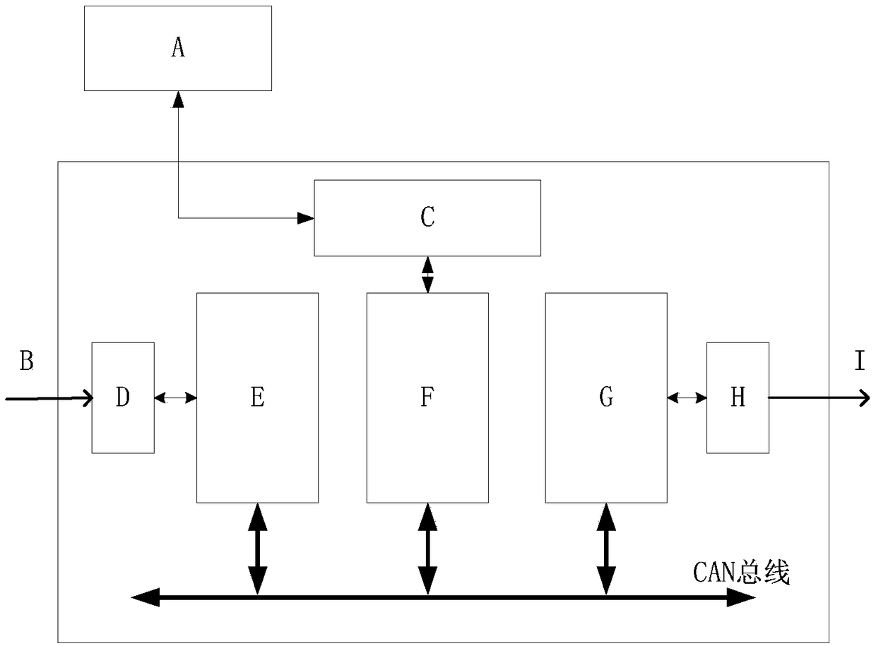
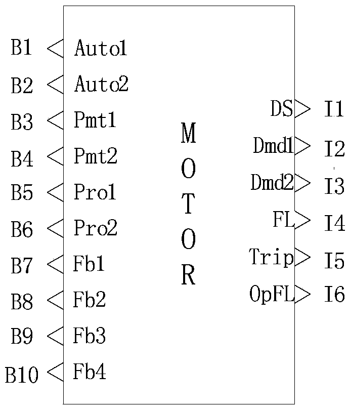
[0093] Such as figure 1 As shown, the drive stage structure of a thermal power unit motor and solenoid valve equipment in the present invention includes an engineer station A, a data exchange module C, an input terminal module D, an input module E, a control module F, an output module G, and an output terminal module H , input signal group B and output signal group I; said engineer station A and data exchange module C are connected by Ethernet line, input signal group B is connected to input terminal module D by signal line, and input terminal module D is connected by 8-bit parallel data The line is connected to the input module E, the output module G is connected to the output terminal module H through an 8-bit parallel data line, and the output channel of the output terminal module H transmits the output signal group ...


PUM


Abstract

The invention discloses a thermal power generating unit motor and electromagnetic valve type equipment driving stage structure and method. The driving stage structure comprises an engineer station, the engineer station is connected with the data exchange module through an Ethernet line, the input signal group is connected with the input terminal module through a signal line, the input terminal module is connected with the input module, the output module is connected with the output terminal module, and an output channel of the output terminal module transmits the output signal group to external equipment through an output data channel. The input module, the control module and the output module are connected to a system bus in parallel, and the data exchange module is connected with the control module. The invention further discloses a driving method of the driving stage structure. The equipment driving level connection structure is simple, the driving control modes are diverse, the pulse instruction and the single control length instruction can be switched at any time, the pulse width can be set, and the functions of starting permission condition limitation, stopping permission condition limitation, protection starting, protection stopping, automatic judgment of feedback signal faults, automatic judgment of equipment tripping and automatic judgment of operation failures are achieved.

Description

technical field [0001] The invention relates to the technical field of power plant control, in particular to a drive stage structure and method for motors of thermal power units and solenoid valves. Background technique [0002] The production process of thermal power units includes a large number of motors and solenoid valves. This type of equipment is controlled by pulse signals or level signals to start and stop, with start and stop feedback, and there is no stop control and feedback in the control process. For example, various feed water pumps of power plants (condensate water pumps, reverse osmosis feed water pumps, integrated water pumps, etc.), motors and motors of various voltage levels (induced fans, primary fans, sealed fans), and various types of solenoid valves. The operation control strategies and methods of these motors and solenoid valves directly determine the power generation efficiency of the unit, and are crucial to the safe operation and protection of the...

Claims


Application Information

Patent Timeline
IPC IPC(8): G06F13/12G06F9/30
CPCG06F9/30003G06F13/124
Inventor 李晓博高海东高少华高龙军马乐崔逸群王宾
Owner XIAN THERMAL POWER RES INST CO LTD
Learn More