
Mass transfer method and device for electronic elements

A technology of electronic components and transfer methods, applied in the direction of electrical components, circuits, semiconductor devices, etc.

Active Publication Date: 2019-03-08
GUANGDONG UNIV OF TECH
View PDF6 Cites 12 Cited by
  • Summary
  • Abstract
  • Description
  • Claims
  • Application Information

AI Technical Summary

Problems solved by technology

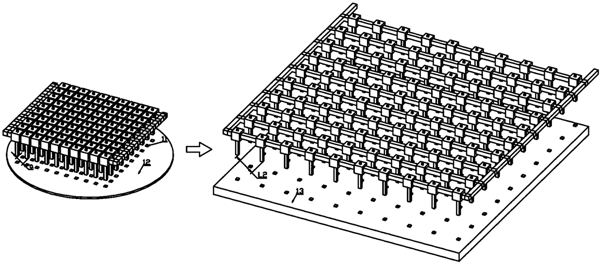
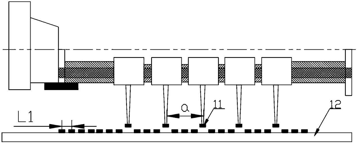
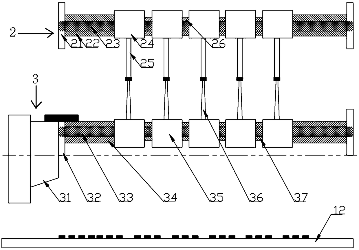
[0006] The purpose of the present invention is to solve the above problems and propose a mass transfer method and device for electronic components, which overcomes the problem that the prior art cannot mass-transfer Micro-LEDs with fully controllable spacing on target substrates such as panels or wafers.

Method used


Image

  • Mass transfer method and device for electronic elements
  • Mass transfer method and device for electronic elements
  • Mass transfer method and device for electronic elements

Examples


Embodiment Construction

[0038] The technical solutions of the present invention will be further described below in conjunction with the accompanying drawings and through specific embodiments.

[0039] A mass transfer method for electronic components, comprising the following steps:

[0040] Step 1, drive the XY axis of the motion platform for machine vision alignment, and the Z axis to keep the flip-chip transfer head at a certain distance from the Micro-LED, and apply external force through the clamping devices at both ends according to the distance between the Micro-LED on the substrate to be grasped The elastic material is longitudinally deformed, the flip-chip transfer head is precisely aligned with the substrate Micro-LED, and the substrate Micro-LED is grasped when a positive voltage is applied to the flip-chip transfer head;

[0041] Step 2: Turn over the flip-chip transfer head, and at the same time, the die-bonding transfer head clamps the substrate Micro-LED up and down, grasp the LED when ...


PUM


Abstract

The invention relates to a mass transfer device for electronic elements. The device comprises a die bonding welding arm, a flip chip welding arm, external physical field devices and an operation table. The die bonding welding arm and the flip chip welding arm are electrically connected to the operation table, respectively; the external physical field devices are arranged on the two sides of the die bonding welding arm and the flip chip welding arm respectively; a flip chip rotating motor is arranged on one side of a flip-chip two-end clamping device; the flip-chip two-end clamping device is arranged on two sides of a flip-chip ejector rod; a flip-chip guide rail is arranged on the flip-chip ejector rod, a flip-chip bracket is movably arranged on the flip-chip guide rail; a flip-chip transfer head is arranged on the flip-chip bracket; and an flip-chip elastic material is arranged between the adjacent flip-chip brackets. The invention aims to provide a mass transfer method and device forelectronic elements. The device in the invention is simple, the efficiency is improved by a2c times, the distance between the electronic elements is completely controllable and a mass of the electronic elements are transferred to the target substrate. The method and the device have a great application value in the field of semiconductor manufacturing.

Description

technical field [0001] The invention relates to the field of semiconductor manufacturing, in particular to a mass transfer method and device for electronic components. Background technique [0002] Micro-LED is a display technology that miniaturizes and matrixes the LED structure, and individually drives and addresses each pixel. Since Micro-LED technology is superior to LCD and OLED technology in various indicators such as brightness, life, contrast, response time, energy consumption, viewing angle and resolution, it is regarded as a new generation of display technology that can surpass OLED and traditional LED. . However, due to the requirements of extremely high efficiency, 99.9999% yield and transfer accuracy within plus or minus 0.5 μm in the packaging process, the size of Micro-LED components is basically less than 50 μm and the number is tens of thousands to millions. -A core technical problem that still needs to be overcome in the process of LED industrialization i...

Claims


Application Information

Patent Timeline
Patent Type & Authority Applications(China)
IPC IPC(8): H01L21/67H01L33/48H01L33/62
CPCH01L21/67144H01L33/48H01L33/62
Inventor 陈新贺云波麦锡全崔成强刘强张凯高健杨志军陈桪陈云汤晖张昱
Owner GUANGDONG UNIV OF TECH
Learn More