Cabinet anti-condensation method and device thereof

An anti-condensation and cabinet technology, applied in the operation mode of machines, refrigerators, machines using electrical/magnetic effects, etc., can solve the problems of inconvenient wiring on site, equipment condensation, equipment aging, etc., to prevent the internal insulation of equipment reduced effect

Pending Publication Date: 2019-03-08
辽宁中天智控技术有限公司
View PDF0 Cites 9 Cited by
  • Summary
  • Abstract
  • Description
  • Claims
  • Application Information

AI Technical Summary

Problems solved by technology

Although this method strengthens the anti-condensation measures, it also brings power loss and waste.
[0006] Common dehumidification equipment uses external sensors to measure ambient temperature and humidity, which is inconvenient for on-site wiring
At the same time, the traditional dehumidifier control method is to set the temperature and humidity values ​​through function keys and software menus. The dehumidifier controls the heater and refrigerator to make the ambient temperature higher than the set temperature and lower than the set humidity. This method does not completely solve the problem of equipment condensation. When the ambient temperature is higher than the set temperature and the ambient humidity is lower than the set humidity, the environmental space may also condense. The electrical equipment or lines in the environmental space Nodes may also be exposed to moisture due to condensation, oxidizing electrical equipment or line nodes, resulting in accelerated aging of equipment, and even the risk of electrical short circuits

Method used


Image

  • Cabinet anti-condensation method and device thereof
  • Cabinet anti-condensation method and device thereof
  • Cabinet anti-condensation method and device thereof

Examples


Embodiment Construction

[0040] The present invention will be further elaborated below in conjunction with the accompanying drawings of the description.

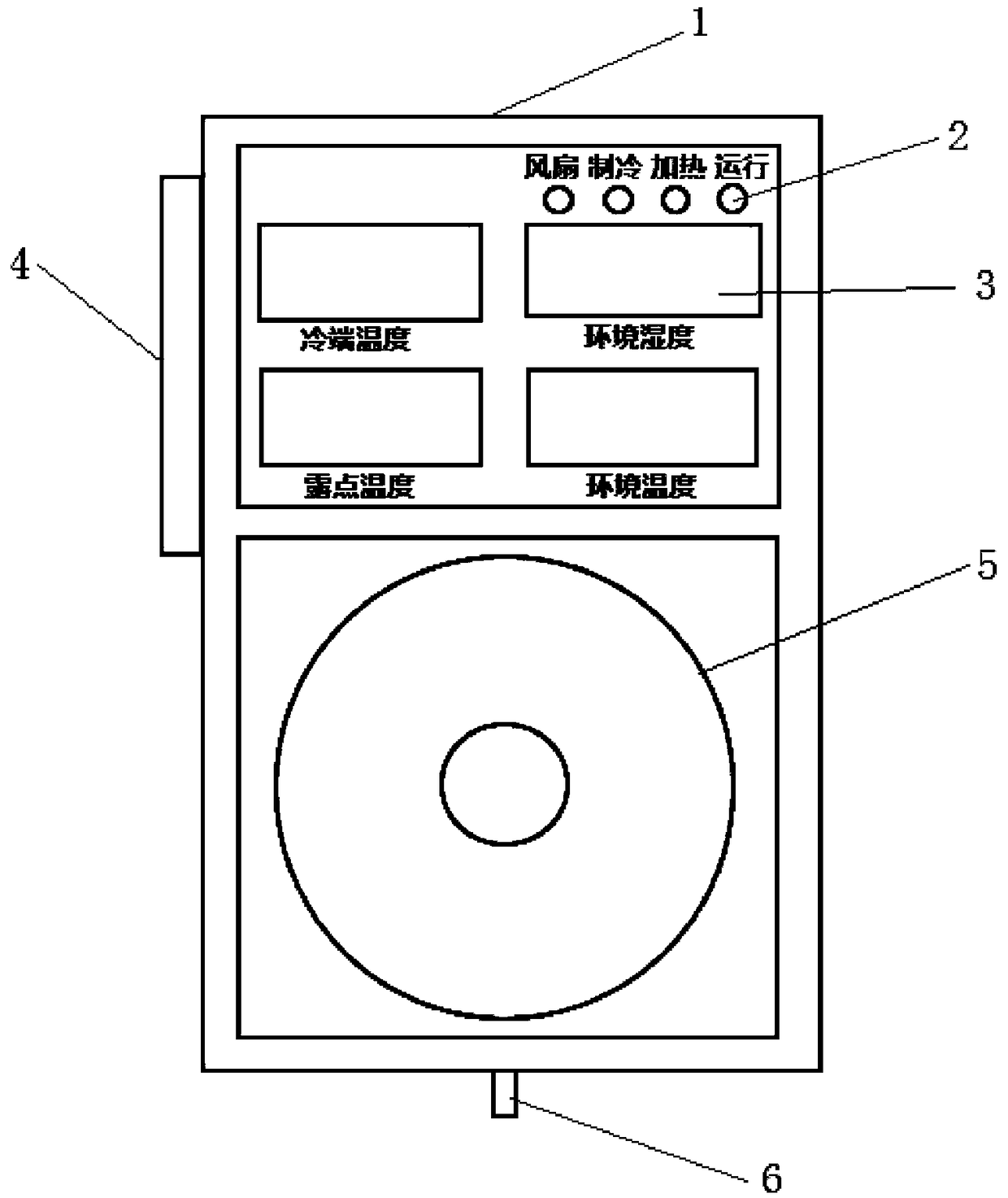
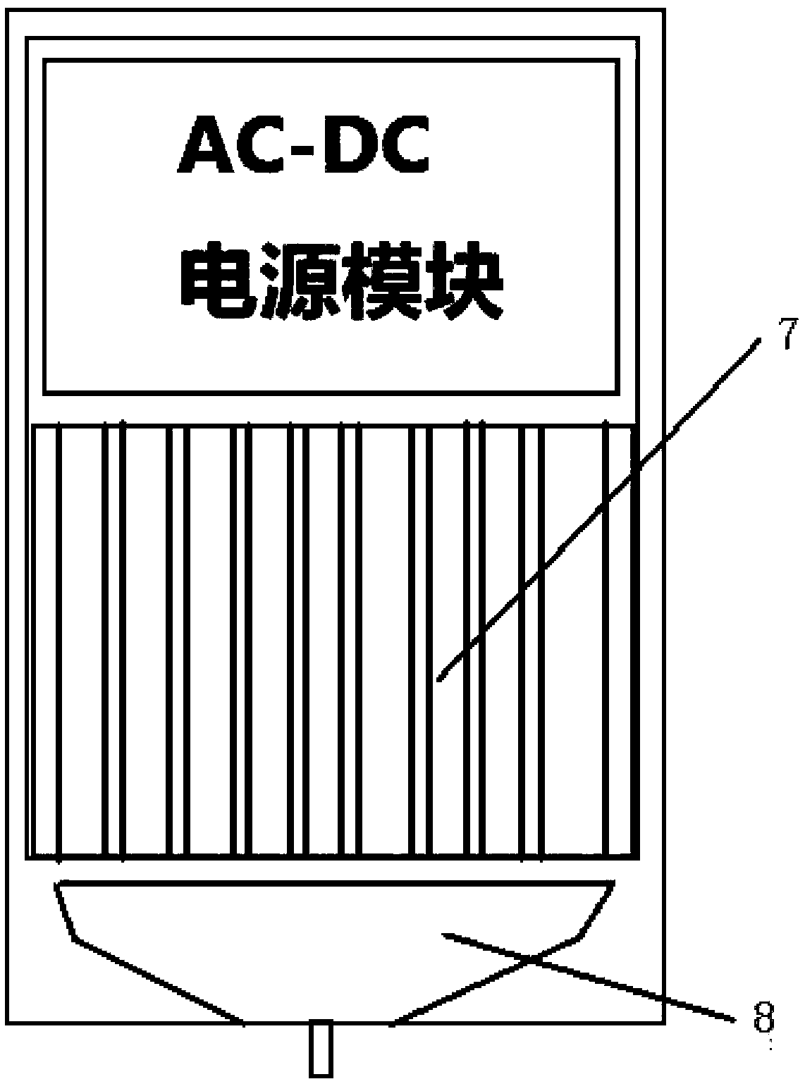
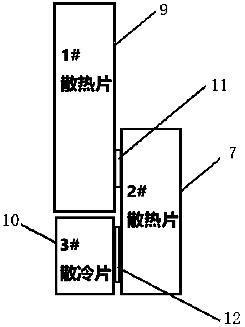
[0041] Such as Figure 1~3 As shown, a cabinet anti-condensation device of the present invention is installed in a cabinet, including a cabinet, first to third heat sinks installed in the cabinet, a refrigeration unit, a heating unit, a drainage unit and a control unit, wherein the first The heat sink is set above the third heat sink, the second heat sink is set on the side of the first and third heat sinks, the heating unit is installed between the first and second heat sinks, and the cooling unit is installed between the second and third heat sinks In between, the third heat sink contacts the cold end of the refrigeration unit, and the second heat sink contacts the hot end of the refrigeration unit; the drainage unit is installed at the inner bottom of the casing; the main control board of the refrigeration unit is installed on the inner side of t...


PUM


Abstract

The invention relates to a cabinet anti-condensation method and device thereof. The device comprises a case, first cooling fins to third cooling fins, a refrigeration unit, a heating unit, a drainageunit and a control unit; the first cooling fins are arranged above the third cooling fin, the second cooling fins are arranged at the sides of the first cooling fins and the third cooling fins; a heating unit is arranged between the first cooling fins and the second cooling fins; the refrigeration unit is arranged between the second cooling fins and the third cooling fins; the third cooling fins contact with a cold end of the refrigeration unit, and the second cooling fins contact with a hot end of the refrigeration unit; the drainage unit is arranged at the bottom in the case, the main control board of the refrigeration unit is arranged at the inner side of the panel of the case, and a fan is arranged at the lower part of the panel; a connection terminal of a control unit is arranged at an outside of the case. The dew point temperature is damaged by utilizing two ways of heating and refrigerating and dehumidification, so that the environment temperature always cannot close to or is lower than the dew point temperature; the moisture in the current environment air cannot condense, an operation of artificially setting temperature and humidity value can be avoided, and the intelligentwork is realized.

Description

technical field [0001] The invention relates to an anti-condensation technology, in particular to a cabinet anti-condensation method and a device thereof. Background technique [0002] For a long time, the climate in various parts of our country has been diverse, and the local temperature and humidity have changed rapidly with the weather. At the same time, due to the structure of the outdoor electrical equipment (terminal box, control box, switch cabinet, power distribution cabinet, etc.), coupled with poor sealing and aging Due to factors such as irregular plugging and other factors, internal moisture and box corrosion often occur. The insulation distance of the outdoor chassis is tight. Once it is wet, there will be problems such as power tripping, false protection signals, and grounding, which will shorten the service life of the equipment. If the air is too humid and causes condensation, it will also cause serious consequences such as short circuit of the power supply ...

Claims


Application Information

Patent Timeline
Patent Type & Authority Applications(China)
IPC IPC(8): H05K7/20F25B21/02
CPCH05K7/207F25B21/02
Inventor 郑学明张智鹏
Owner 辽宁中天智控技术有限公司
Why Eureka
Try Eureka